
Image layout

a technology of image layout and printing environment, applied in printing, printing, electromagnetography, etc., can solve the problems of complex and inefficient workflow, manual intervention of clients' prints from multiple printers, and complex and expensive mechanical substrate handling systems

Active Publication Date: 2016-05-26
HEWLETT PACKARD INDIGO BV
View PDF7 Cites 0 Cited by
  • Summary
  • Abstract
  • Description
  • Claims
  • Application Information

AI Technical Summary

Benefits of technology

The patent describes a printing production environment and how it can handle different customer orders with different number of images and different print sizes. The method includes a web layout module that can automatically create a layout for the images based on their size and position. The layout includes information about where the images will be printed and how to control the cutting of the sheets. This invention helps to improve the efficiency and accuracy of printing production.

Problems solved by technology

In web-based printing production environments the production of different size prints for a single client can lead to complex and inefficient workflows.
Collating a client's prints from multiple printers requires manual intervention or complex and expensive mechanical substrate handling systems.

Method used


Image

  • Image layout
  • Image layout
  • Image layout

Examples


Embodiment Construction

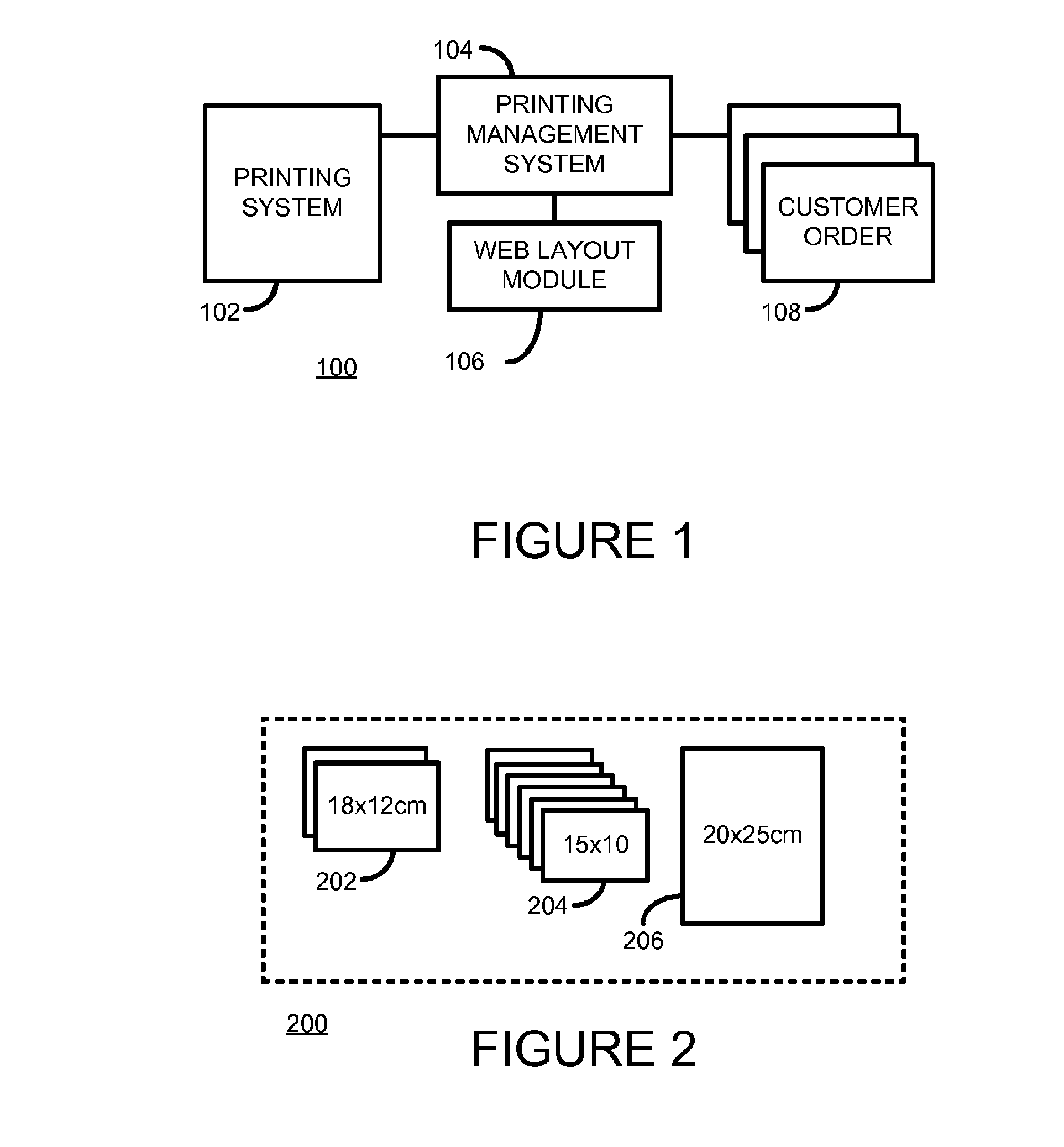
[0015]In some printing production environments customer orders may include content to be printed of differing sizes. Content may include images, photographs, documents, or the like. For convenience herein, however, the term ‘image’ is used generally to cover, as appropriate, any suitable type of content to be printed or suitable type of printed content.

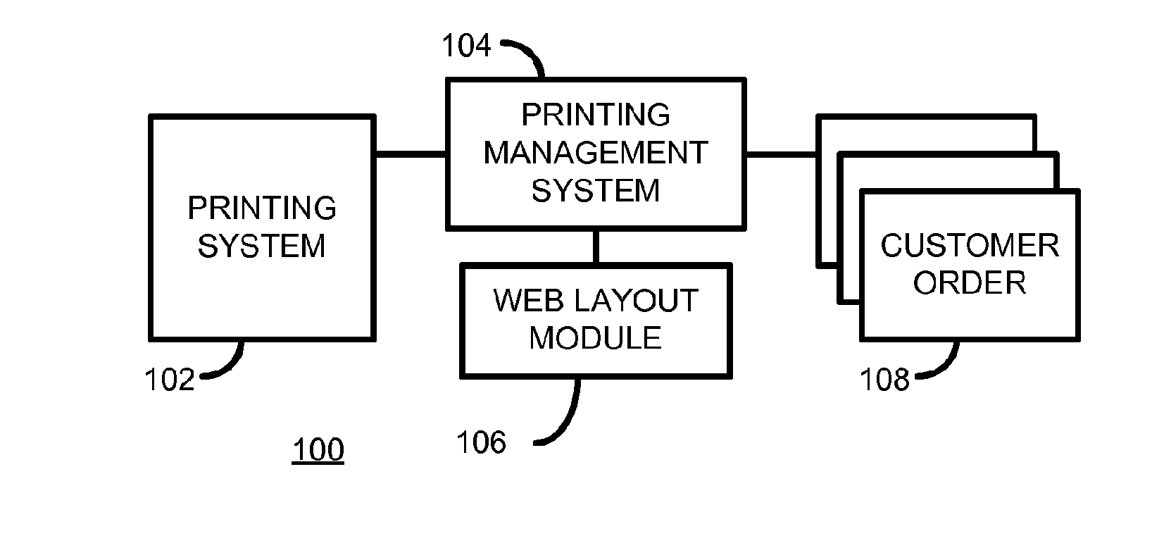
[0016]FIG. 1 shows an illustrative block diagram of a printing production environment 100 according to one example. The printing production environment 100 includes a printing system 102 for generating printed images. In one example the printing system 102 is a printing system that prints on rolls or webs of substrate.

[0017]The printing system 102 may in some examples include one or multiple finishing modules (not shown) for performing post-processing operations on printed images generated by the printing system. Example finishing modules include cutters, laminators, and stackers. In one example the printing production environment 100...


PUM


Abstract

According to one example, there is provided a web layout apparatus to generate a web layout of a set of images to be printed.

Description

BACKGROUND[0001]In web-based printing production environments the production of different size prints for a single client can lead to complex and inefficient workflows. For example, printing production environments are generally configured such that different physical printers are used to produce prints of different sizes on separate webs of substrate. Each printing system typically has its own associated cutting equipment to separate each individual print from each web.[0002]Collating a client's prints from multiple printers requires manual intervention or complex and expensive mechanical substrate handling systems.BRIEF DESCRIPTION[0003]Examples, or embodiments, of the invention will now be described, by way of non-limiting example only, with reference to the accompanying drawings, in which:[0004]FIG. 1 shows an illustrative block diagram of a printing production environment according to one example;[0005]FIG. 2 illustrates one example of a customer order having a number of images...

Claims


Application Information

Patent Timeline
Patent Type & Authority Applications(United States)
IPC IPC(8): B41J11/66B41J15/00
CPCB41J15/00B41J11/663B41F33/00B41F33/0009B41F13/58B41F13/60G03G15/36G03G2215/00814B41J11/68B41J11/70B41J15/04G03G15/6523H04N1/00132H04N1/00453
Inventor YASINOVER, DAVIDMEIRI, ILANKENT, ITZIK
Owner HEWLETT PACKARD INDIGO BV
Learn More