Fuel tank access door systems and methods

a technology for accessing doors and fuel tanks, which is applied in the direction of fuel tank safety measures, aircraft accessories, aircraft lighting protectors, etc., can solve problems such as corrosion between the wing and the access door surface, and achieve the effects of reducing maintenance costs, simplifying installation, and improving safety

Active Publication Date: 2017-08-01
TEXTRON INNOVATIONS
View PDF34 Cites 1 Cited by
  • Summary
  • Abstract
  • Description
  • Claims
  • Application Information

AI Technical Summary

Benefits of technology

[0008]The present fuel tank access door systems and methods improve safety by minimizing the risk of lightning attachment, p-static build up and fuel pooling at the access door. These benefits are achieved in some systems and methods, for example, by completely encapsulating an outer metallic access door with a dielectric material and / or providing the inner fuel tank access door with at least one drainage feature. The disclosed systems and methods also decrease maintenance costs and simplify installation by eliminating the need for p-static paint, which allows the aircraft skin to retain its corrosion preventative primer.
[0009]In addition, inner fuel tank access doors of the present system have form factors or geometries that eliminate a cavity between the inner and outer fuel tank access doors. This cavity, found in most existing systems, is intended to reduce weight, but it is capable of trapping moisture and encouraging corrosion on the outer fuel tank access door. In the present systems, the inner fuel tank access door weight is reduced by dishing out the top side of the inner fuel tank access door and providing at least one drainage feature. By sloping the drainage path substantially along the longitudinal axis of the wing, which is tilted toward the aircraft fuselage, fuel is prevented from being trapped on top of the inner access door as the fuel tank empties. This reduces or eliminates the fire hazard associated with fuel pooling.

Problems solved by technology

This design works well for p-static; however, it results in galvanic action causing corrosion between the wing and access door surfaces.

Method used


Image

  • Fuel tank access door systems and methods
  • Fuel tank access door systems and methods
  • Fuel tank access door systems and methods

Examples


Embodiment Construction

[0025]In general, the terms and phrases used herein have their art-recognized meaning, which can be found by reference to standard texts, journal references and contexts known to those skilled in the art. The following definitions are provided to clarify their specific use in the context of this description.

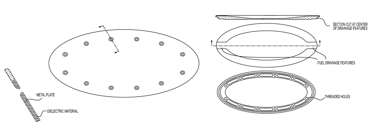
[0026]As used herein, “top” and “bottom” surfaces of fuel tank access doors are described relative to the upright aircraft orientation. Thus, the top surface of the inner fuel tank door, which faces the inside of a fuel tank, forms the top of the fuel tank access door stack and the bottom surface of the outer fuel tank door, which faces outside the aircraft, forms the bottom of the fuel tank access door stack.

[0027]A “system” is a combination of components operably connected to produce one or more desired functions. A “component” is used broadly to refer to an individual part of a system.

[0028]“Encapsulated” refers to the orientation of one structure such that it is at least part...


PUM


Abstract

Aircraft fuel tank access door systems and methods incorporating one or more of an outer fuel tank access door completely encapsulated by a dielectric material and an inner fuel tank access door comprising at least one drainage feature are disclosed. These systems and methods reduce or prevent (i) fuel pooling on the inner fuel tank access door, (ii) moisture pooling between the inner and outer fuel tank access doors, and (iii) p-static build up and lightning attachment to the outer fuel tank access door to increase safety, reduce the likelihood of corrosion and ease installation of the fuel tank access door system.

Description

CROSS-REFERENCE TO RELATED APPLICATION[0001]This application claims the benefit of priority from U.S. Provisional Patent Application No. 62 / 019,746, filed Jul. 1, 2014, which is hereby incorporated by reference in its entirety.BACKGROUND OF THE INVENTION[0002]1. Field of the Invention[0003]The invention relates generally to the field of aircraft fuel tank access doors. More specifically, the present invention relates to fuel tank access doors having features that protect against lightning, precipitation static, and corrosion.[0004]2. Description of the Related Art[0005]Aircraft wings are equipped on their undersides with fuel tank access doors that allow for inspection of fuel tanks located within the wings. Generally, each access door includes an inner door located inside the wing and an outer door located outside the wing. The inner and outer doors may be secured to the wing by clamping a portion of the aircraft skin between the doors, and fastening the doors directly to one anoth...

Claims


Application Information

Patent Timeline
Patent Type & Authority Patents(United States)
IPC IPC(8): B64C3/34B64D45/02B64C1/14B64D37/32
CPCB64C3/34B64C1/1446B64D37/32B64D45/02Y02T50/44Y02T50/40
Inventor MARTIN, BILLY M.HARRISON, TIMOTHY E.LO, ZAIPARKS, BRANDON L.
Owner TEXTRON INNOVATIONS
Why Eureka
Try Eureka