
Wireless battery charger and charge-receiving device

a charging device and wireless technology, applied in electric vehicles, electric power, transportation and packaging, etc., can solve the problems of portable electronic devices that are susceptible to falling, scratching, crushing, etc., and achieve the effect of prolonging the use time of the devi

Active Publication Date: 2017-07-04
OTTER PRODS
View PDF36 Cites 42 Cited by
  • Summary
  • Abstract
  • Description
  • Claims
  • Application Information

AI Technical Summary

Benefits of technology

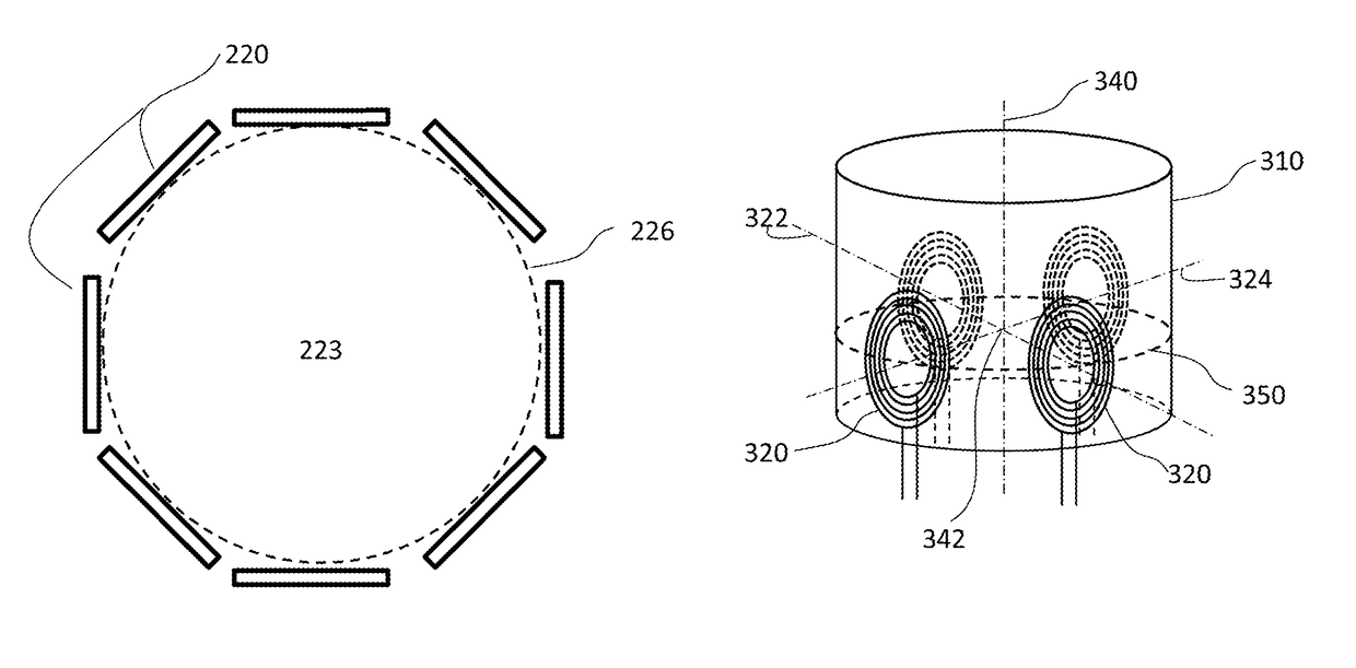
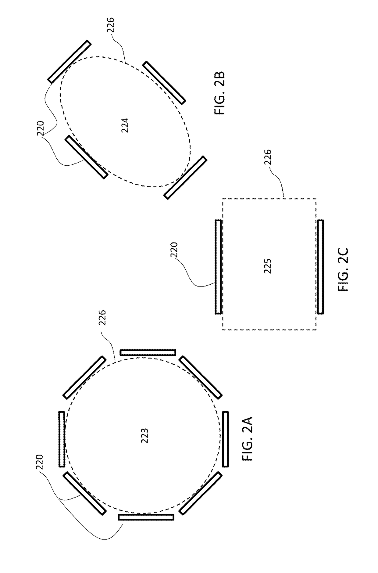
[0018]When its user is in a vehicle, a mobile device may commonly be placed in the vehicle's cupholder. Typically, different users may place the mobile device in the cupholder in any of an infinite number of orientations. For example, a vehicle driver may place a mobile device in the cupholder in an orientation convenient for readability or easy access from the driver seat, or may casually dump the mobile device in the cupholder without regard to its orientation. A passenger may wish to use the same cupholder to charge a second device, in addition to the driver's device. If the passenger is the sole user of the cupholder for charging purposes, the device orientation may be different from the orientation the driver would use. Where prior cupholder based wireless chargers may fail to address a plurality of portable device orientations, the present disclosure presents a wireless charger for a portable electronic device in which a user's portable electronic device could, automatically, be wirelessly while in a variety of orientations, thus prolonging the use time of the device with minimum inconvenience to the device user.

Problems solved by technology

However, such wireless chargers do not permit multiple orientations of a chargeable device.
Similarly, portable electronic devices are susceptible to dropping, scratching, crushing, and other damage.

Method used


Image

  • Wireless battery charger and charge-receiving device
  • Wireless battery charger and charge-receiving device
  • Wireless battery charger and charge-receiving device

Examples


Embodiment Construction

[0040]The detailed description set forth below in connection with the appended drawings is intended as a description of exemplary embodiments of the present disclosure and is not intended to represent the only embodiments in which the present disclosure can be practiced. The term “exemplary” used throughout this description means “serving as an example, instance, or illustration,” and should not necessarily be construed as preferred or advantageous over other exemplary embodiments. The detailed description includes specific details for the purpose of providing a thorough understanding of the exemplary embodiments of the disclosure. It will be apparent to those skilled in the art that the exemplary embodiments of the disclosure may be practiced without these specific details. In some instances, well-known structures and devices are shown in block diagram form in order to avoid obscuring the novelty of the exemplary embodiments presented herein.

[0041]In one application, for the conven...


PUM


Abstract

A wireless charger includes a plurality of conductive coils and electronic circuitry. The coils are disposed around a perimeter and face a generally central area of the perimeter. The coils are connected to and controlled by the electronic circuitry, which includes an electric power receiving circuit and a coil controller. The electric power receiving circuit receives electrical power from an external source and conditions the power for provision to the coil controller. The coil controller controls provision of an oscillating current to select coils within the plurality of coils. A protective enclosure or portable electronic device may have receiving coils disposed at its sides for corresponding to at least two of the conductive coils of the wireless charger.

Description

CROSS-REFERENCE TO RELATED APPLICATIONS[0001]This application claims the benefit of U.S. Provisional Patent Application Ser. No. 61 / 991,279; filed May 9, 2014; which is hereby incorporated by reference in its entirety.BACKGROUND[0002]Portable electronic devices generally require power to operate. The electrical power is often supplied at least partly by one or more batteries. When power in the battery is depleted, a user may replace the battery or recharge it. Recharging the battery often involves physically attaching the battery or the portable electronic device to a power source, such as a standard electrical outlet, via a power cable.[0003]An electrical battery typically includes one or more electrochemical cells that convert stored chemical energy into electrical energy. When the battery is attached to a load (e.g., an electric circuit such as found in a mobile phone), elements within the battery are changed due to a chemical reaction within the battery in order to allow ions (a...

Claims


Application Information

Patent Timeline
Patent Type & Authority Patents(United States)
IPC IPC(8): H02J7/00H02J50/60H02J7/02H02J50/80H02J50/10
CPCH02J50/60H02J7/007H02J7/0044H02J7/025H02J50/10H02J50/80H02J50/70H02J50/90H02J50/12H02J7/0042
Inventor DAVISON, THOMAS J.LARSEN, JAMES C.
Owner OTTER PRODS
Learn More