
Pivot for timepiece mechanism

a timepiece mechanism and pivoting technology, applied in the direction of instruments, horology, protection against external influences, etc., can solve the problems of high production cost of pivoting, and achieve the effect of high reliability, precise repositioning, and good absorption qualities

Active Publication Date: 2017-06-20
NIVAROX FAR
View PDF16 Cites 4 Cited by
  • Summary
  • Abstract
  • Description
  • Claims
  • Application Information

AI Technical Summary

Benefits of technology

This design achieves reliable shock absorption with reduced friction and wear, precise repositioning, and simplified assembly, while minimizing the number of components and eliminating lubrication needs, resulting in a more cost-effective and precise timepiece mechanism.

Problems solved by technology

It is expensive to produce pivots, in terms of the number and cost of components and the machining costs of high precision geometric implementations, and the assembly of jewels and shock absorber devices requires particular care.

Method used


Image

  • Pivot for timepiece mechanism
  • Pivot for timepiece mechanism
  • Pivot for timepiece mechanism

Examples


Embodiment Construction

[0048]The invention concerns the field of timepiece mechanisms, and more specifically the pivoting of timepiece wheel sets.

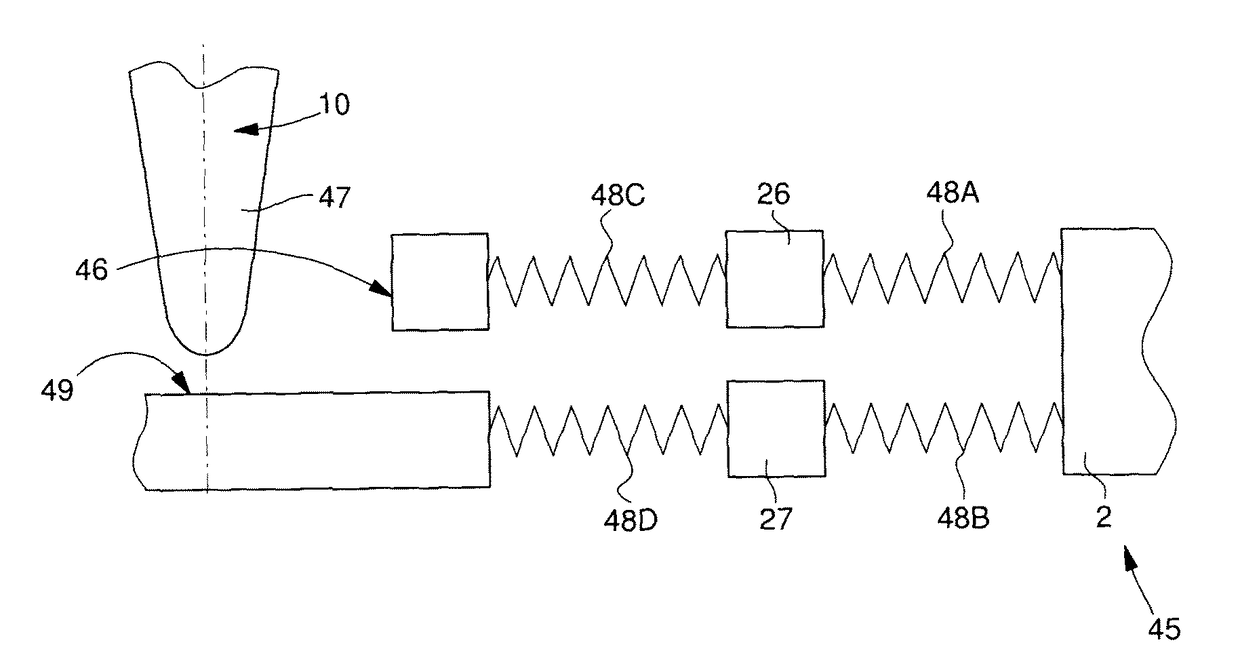
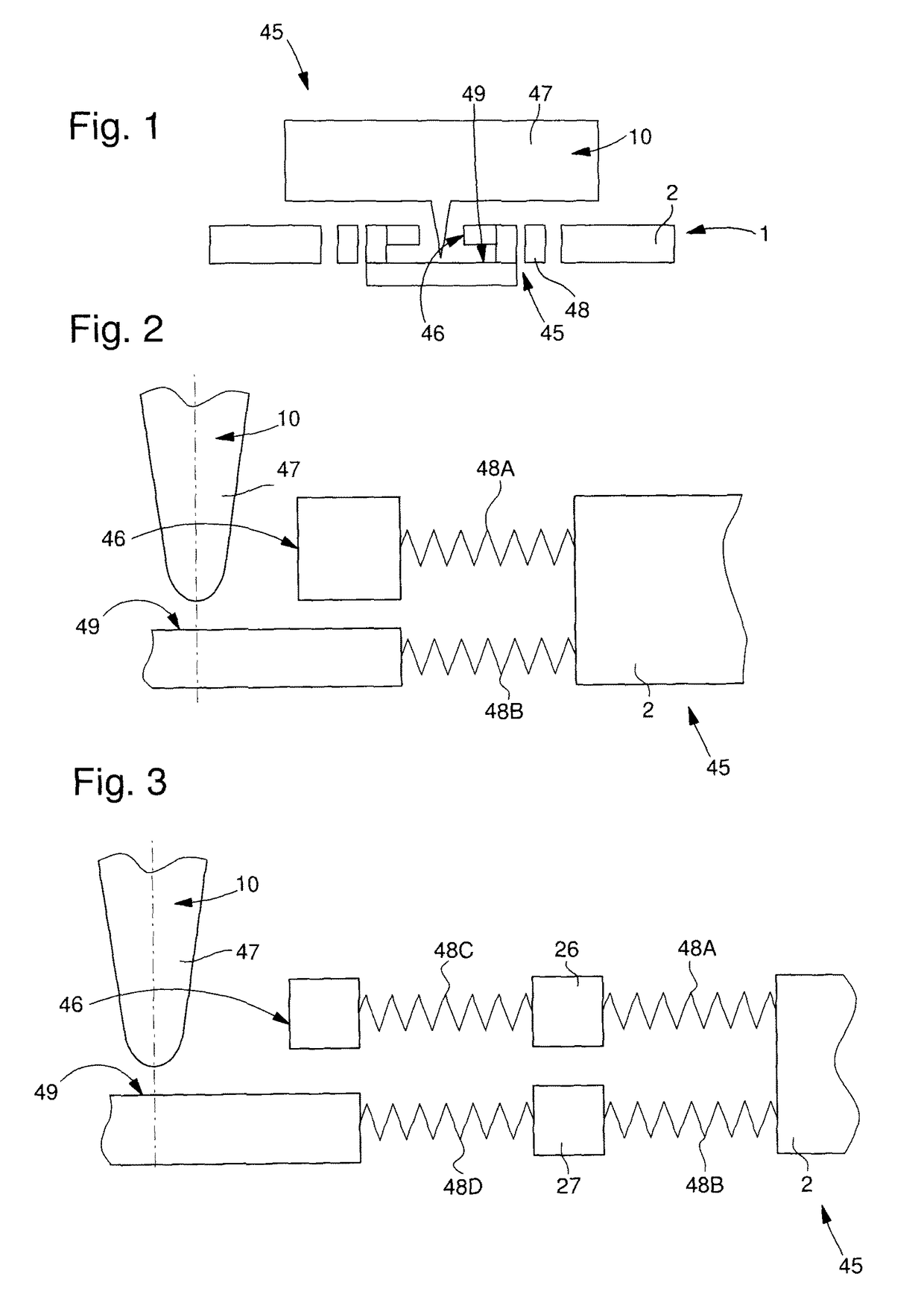
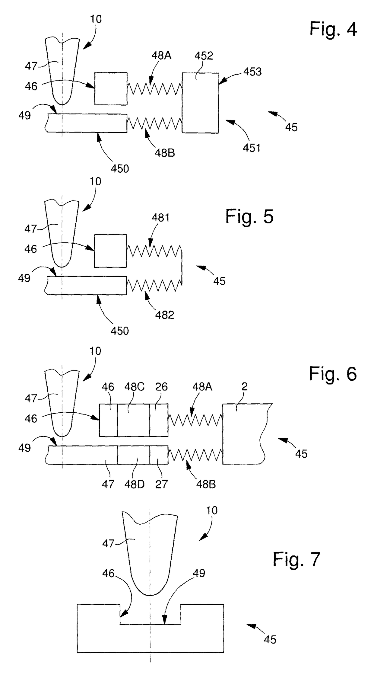
[0049]The invention concerns a pivot 45 for a timepiece mechanism, including a first rotational guide member 46 for radially holding an arbor 47 in a plate 2 and a second front guide member 49 for axially limiting the end of arbor 47. This pivot 45 includes at least one resilient shock absorber 48, which acts on at least the first rotational guide member 46 and / or the second front guide member 49.

[0050]According to the invention, in a first preferred embodiment, this at least one resilient shock absorber 48 is made in a one-piece manner, in a micromachinable material or silicon or quartz or diamond or ruby or corundum, with at least one structural element 451 other than the first rotational guide member 46 and the second front guide 49.

[0051]This structural element 451 may consist in particular of a plate, bridge, cabochon or other element.

[0052]According to the...


PUM


Abstract

A pivot for a timepiece mechanism, including a first rotational guide member for radially holding an arbor in a plate, and a second front guide member for axially limiting an end of the arbor, and including at least one resilient shock absorber acting on at least the first rotational guide member and / or the second front guide member. The resilient shock absorber is made in a one-piece manner in a micromachinable material or in silicon or quartz or diamond with a structural element other than the first rotational guide member and the second front guide member.

Description

CROSS-REFERENCE TO RELATED APPLICATIONS[0001]This is a National phase application in the U.S. of International patent application PCT / EP2014 / 052784 filed Feb. 13, 2014 which claims priority on European patent application No. 13160026.4 filed Mar. 19, 2013. The entire disclosures of the above patent applications are hereby incorporated by reference.FIELD OF THE INVENTION[0002]The invention concerns a pivot for a timepiece mechanism, including a first rotational guide member for radially holding an arbor in a plate, and a second front guide member for axially limiting the end of said arbor, and including at least one resilient shock absorber acting on at least said first rotational guide member and / or said second front guide member, wherein said at least one resilient shock absorber is made in a one-piece manner in a micromachinable material or silicon or quartz or diamond or ruby or corundum with at least one structural element other than said first rotational guide member and said f...

Claims


Application Information

Patent Timeline
Patent Type & Authority Patents(United States)
IPC IPC(8): G04B31/00G04B31/06G04B31/04G04B31/02G04B29/04G04B29/02G04B43/00G04B31/004G04B31/016
CPCG04B31/02G04B29/02G04B29/04G04B31/004G04B31/016G04B31/04G04B31/06G04B43/002
Inventor STRANCZL, MARCHESSLER, THIERRYHELFER, JEAN-LUC
Owner NIVAROX FAR
Learn More