Eyepiece lens and imaging apparatus

a technology which is applied in the field of eyepiece lens and imaging apparatus, can solve the problems of difficult to secure the telecentricity toward the observation object side, and difficult to obtain excellent observation images, and achieve excellent optical performance and excellent correction

Active Publication Date: 2017-06-13
FUJIFILM CORP
View PDF12 Cites 2 Cited by
  • Summary
  • Abstract
  • Description
  • Claims
  • Application Information

AI Technical Summary

Benefits of technology

[0008]In view of the foregoing circumstances, it is an object of the present invention to provide an eyepiece lens configured in small size, and the telecentricity of which toward an observation object side is secured while observation at a high magnification ratio is possible, and in which various aberrations are excellently corrected to have excellent optical performance, and also an imaging apparatus including this eyepiece lens.
[0019]According to the present invention, the number of positive lenses and the number of a negative lens and the arrangement of these lenses are appropriately set in a lens system consisting essentially of four lenses, and a predetermined conditional expression or expressions are satisfied. Therefore, it is possible to achieve an eyepiece lens configured in small size, and the telecentricity of which toward an observation object side is secured while observation at a high magnification ratio is possible, and in which various aberrations are excellently corrected to have excellent optical performance, and also an imaging apparatus including this eyepiece lens.

Problems solved by technology

However, it is difficult to secure the telecentricity toward the observation object side when an eyepiece lens has a high magnification ratio.
Therefore, there is a problem that it is difficult to obtain excellent observation images.
When the magnification of the eyepiece lens, as disclosed in Patent Document 1, is tried to be increased while excellent optical performance is maintained, that is difficult if the eyepiece lens consists of three lenses.

Method used


Image

  • Eyepiece lens and imaging apparatus
  • Eyepiece lens and imaging apparatus
  • Eyepiece lens and imaging apparatus

Examples


example 1

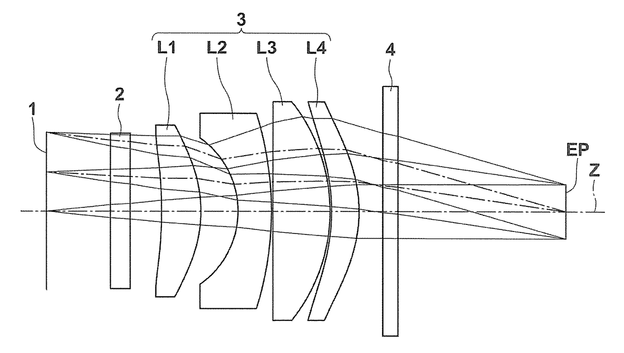
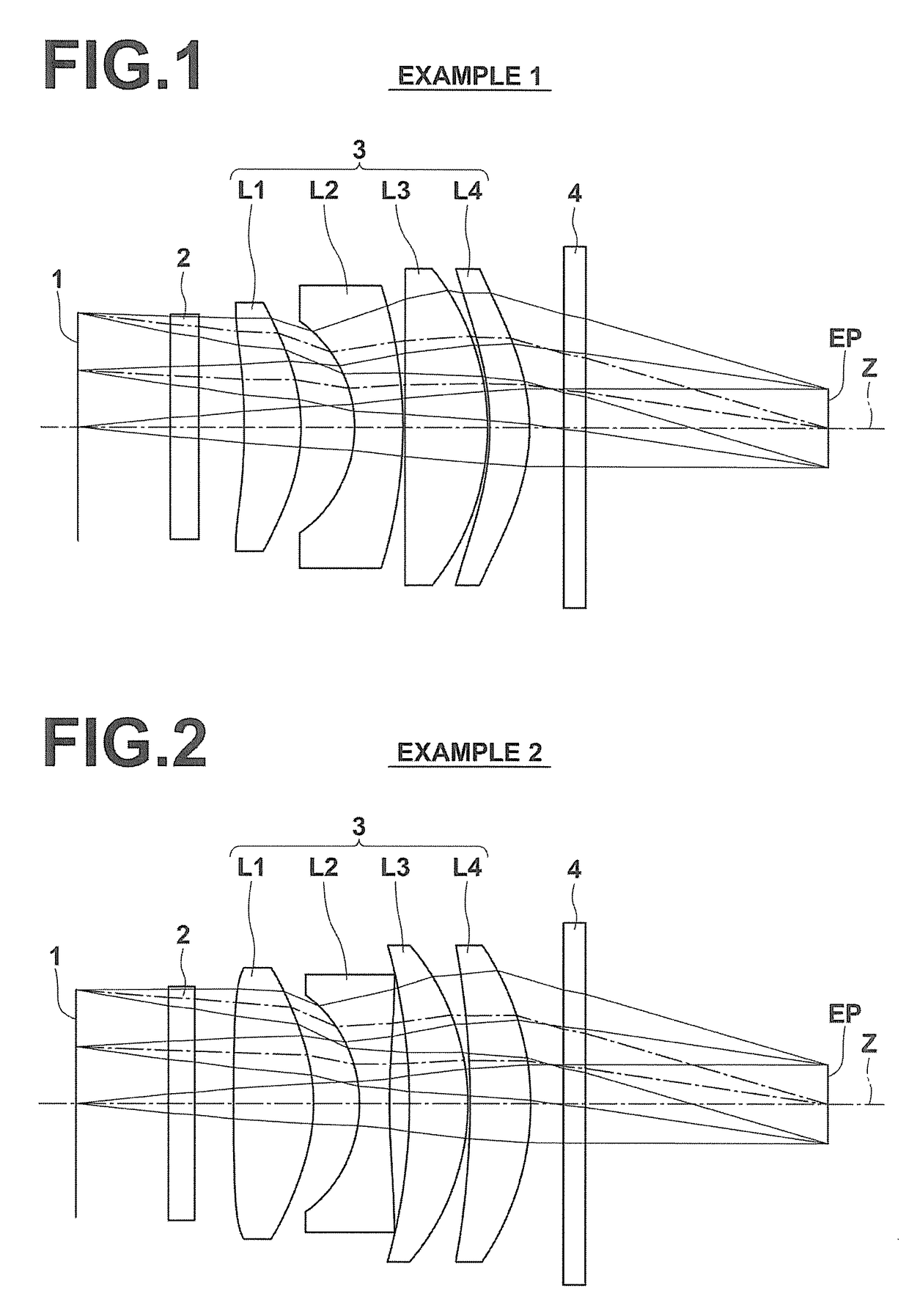
[0057]FIG. 1 is a diagram illustrating the lens configuration of an eyepiece lens in Example 1. Table 1 and Table 2 show basic lens data and specification of the eyepiece lens in Example 1 and aspherical coefficients of the eyepiece lens in Example 1, respectively. In Table 1, a column of Si shows an i-th (i=0, 1, 2, 3, . . . ) surface number when the surface of the image display surface 1 is the 0-th surface and the surface numbers are assigned to sequentially increase toward the eye point side. A column of Ri shows the curvature radius of the i-th surface. A column of Di shows a surface distance, on optical axis Z, between the i-th surface and the (i+1)th surface. A column of Ndj shows the refractive index for d-line (wavelength is 587.6 nm) of a j-th (j=1, 2, 3, . . . ) optical element from the object side. A column of vdj shows the Abbe number for d-line of the j-th optical element from the object side.

[0058]Here, the basic lens data show data including optical members 2 and 4. ...

example 2

[0070]FIG. 2 is a diagram illustrating the lens configuration of an eyepiece lens in Example 2. Table 3 and Table 4 show basic lens data and specification of the eyepiece lens in Example 2 and aspherical coefficients of the eyepiece lens in Example 2, respectively. FIG. 5 illustrates a diagram of a spherical aberration, a diagram of astigmatism, a diagram of distortion, and a diagram of a lateral chromatic aberration of the eyepiece lens in Example 2 in this order from the left side of the paper.

[0071]

TABLE 3EXAMPLE 2SiRiDiNdjνdj0 (OBJ)∞4.191∞1.20001.5168064.202∞1.7500*387.31553.62431.5338955.98*4−8.04162.0768*5−5.91541.35691.6335123.63*631.19600.90147−25.42452.65291.8040046.588−10.61790.10009−38.29132.74801.8348142.7310−12.22971.488311∞1.00001.5168064.2012∞11.000013(EP)∞f17.52DIOPTER−1.01APPARENT FIELD OF31.70VIEW

[0072]

TABLE 4EXAMPLE 2SURFACENUMBER3456KA1.0000000E+001.0000000E+001.0000000E+00 1.0000000E+00A4−3.3491403E−04 4.7681939E−042.8817659E−04−3.1080604E−04A62.4819583E−051.683...

example 3

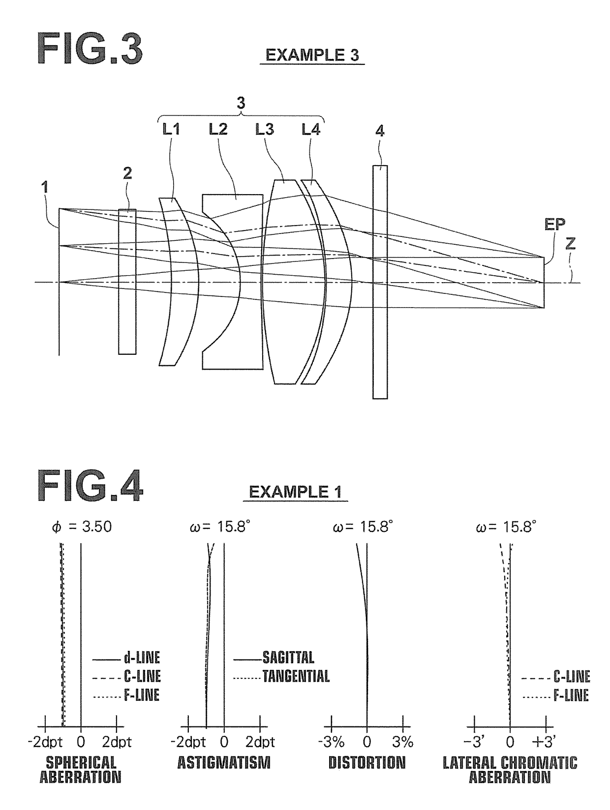
[0073]FIG. 3 is a diagram illustrating the lens configuration of an eyepiece lens in Example 3. Table 5 and Table 6 show basic lens data and specification of the eyepiece lens in Example 3 and aspherical coefficients of the eyepiece lens in Example 3, respectively. FIG. 6 illustrates a diagram of a spherical aberration, a diagram of astigmatism, a diagram of distortion, and a diagram of a lateral chromatic aberration of the eyepiece lens in Example 3 in this order from the left side of the paper.

[0074]

TABLE 5EXAMPLE 3SiRiDiNdjνdj0 (OBJ)∞4.191∞1.20001.5168064.202∞2.50003−19.53141.90311.8502632.274−10.69742.9112*5−5.91961.45021.6335123.63*650.53390.1000729.17274.38731.8348142.738−12.77740.1000*9−16.18581.80001.5338955.98*10−9.09241.488511∞1.00001.5168064.2012∞11.000013 (EP)∞f17.77DIOPTER−1.02APPARENT FIELD OF31.46VIEW

[0075]

TABLE 6EXAMPLE 3SURFACENUMBER56910KA1.0000000E+001.0000000E+001.0000000E+001.0000000E+00A4−7.9724763E−04 −3.8318206E−04 1.3771696E−042.4070790E−04A61.7596716E−059.3...


PUM


Abstract

An eyepiece lens consists essentially of a first lens having positive refractive power, a second lens having negative refractive power, a third lens having positive refractive power, and a fourth lens having positive refractive power in this order from an observation object side. Conditional expression (1): −3.5<f / fA<0.0 is satisfied, wheref: a focal length of an entire system, andfA: a combined focal length of the first lens and the second lens.

Description

CROSS-REFERENCE TO RELATED APPLICATIONS[0001]The present application claims priority under 35 U.S.C. §119 to Japanese Patent Application No. 2014-120240, filed on Jun. 11, 2014. The above application is hereby expressly incorporated by reference, in its entirety, into the present application.BACKGROUND OF THE INVENTION[0002]Field of the Invention[0003]The present invention relates to an eyepiece lens and an imaging apparatus. In particular, the present invention relates to an eyepiece lens appropriate for magnified observation of an image displayed on an image display surface and an imaging apparatus on which this eyepiece lens has been mounted.[0004]Description of the Related Art[0005]Conventionally, eyepiece lenses for magnifying images displayed on image display surfaces of liquid crystal display devices or the like to observe the magnified images by the naked eye were used in viewfinders of digital cameras, video cameras and the like. For example, a 3-element eyepiece lens in wh...

Claims


Application Information

Patent Timeline
Patent Type & Authority Patents(United States)
IPC IPC(8): G02B25/00G02B15/14G02B23/24G02B9/34
CPCG02B25/001
Inventor SAITO, HIROKI
Owner FUJIFILM CORP
Why Eureka
Try Eureka