Linear pipe recovery/lay tensioners and method of using same

a technology of linear pipe and tensioner, which is applied in the direction of pipe laying and repair, mechanical equipment, transportation and packaging, etc., can solve the problems of unbalanced tension command, and achieve the effect of convenient placement of drive assemblies

Active Publication Date: 2017-06-06
CONTROL FLOW
View PDF7 Cites 2 Cited by
  • Summary
  • Abstract
  • Description
  • Claims
  • Application Information

AI Technical Summary

Benefits of technology

[0008]The linear pipe tensioners disclosed herein facilitate one or both of recovery of pipe segments from their locations of installation, and installation of the pipe segments in their locations of installation. In certain embodiments, the linear pipe tensioner comprise upper and lower frames, the upper frame having an upper track assembly and the lower frame having a lower track assembly. The upper and lower frames are pivotally connected to each other to facilitate movement of the upper frame and, thus, the upper track, between a closed position and a plurality of opened positions. Movement of the upper frame facilitates placement of a pipe segment between the upper and lower tracks.
[0011]In additional embodiments, which may or may not include one or more of the features discussed above, two drive assemblies move the tracks which, in turn, linearly move a pipe segment through the linear pipe tensioners. The two drive assemblies are operatively associated with a hydraulic motor or pump and a valve. The valve facilitates placing the drive assemblies in either series or parallel such that the two drive assemblies can rotate at substantially the same rate or at different rates. In these embodiments, the structural components identified above in this Summary can also be part of the linear pipe tensioners, although they are not required.

Problems solved by technology

The tension command will become unbalanced and the control system will drive the pumps producing pressure to the hydraulic motors to bring the tension back into line.

Method used


Image

  • Linear pipe recovery/lay tensioners and method of using same
  • Linear pipe recovery/lay tensioners and method of using same
  • Linear pipe recovery/lay tensioners and method of using same

Examples


Embodiment Construction

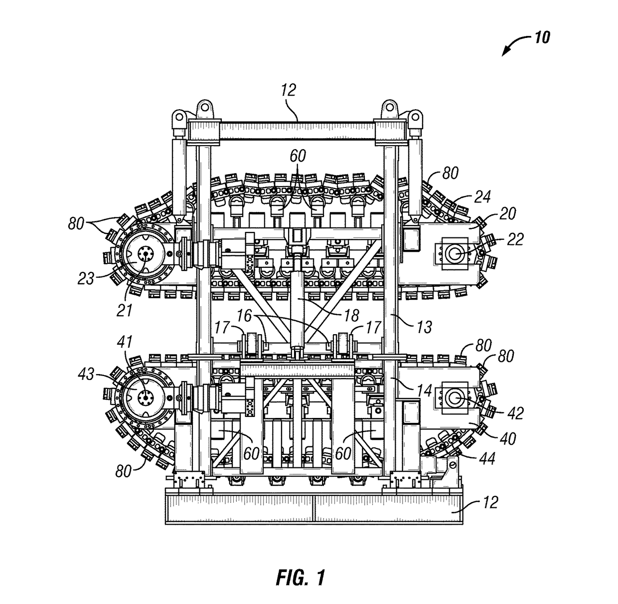
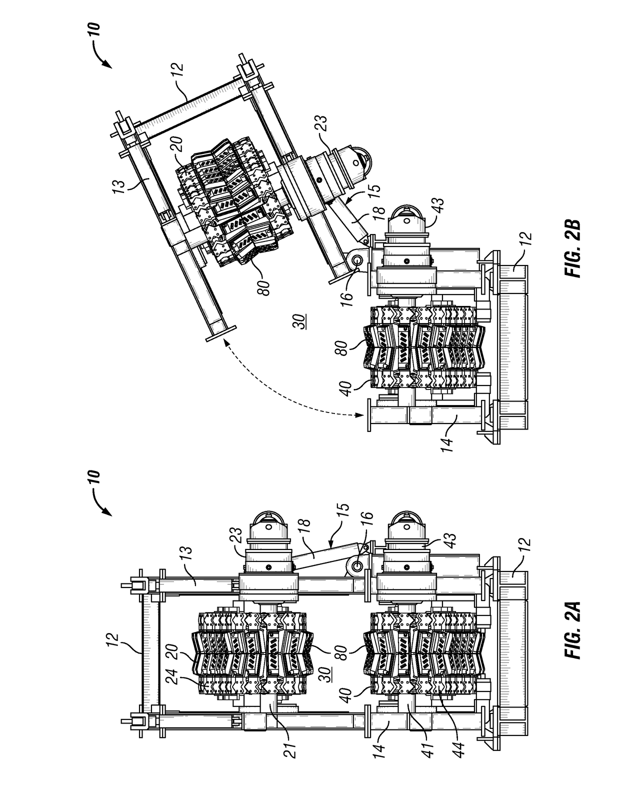
[0029]Referring now to FIGS. 1-10, in one specific embodiment linear pipe tensioner 10 includes frame 12. In this particular embodiment, frame 12 comprises upper frame member 13 and lower frame member 14 rotatably connected to each other by pivot assembly 15. As shown in FIGS. 1, 2A, and 2B, pivot assembly 15 comprises two hinge members comprising pins 16 inserted through brackets 17, and cylinder 18. Pivot assembly 15 permits the movement of upper track assembly 20 along the trajectory of the arrow shown in FIG. 2B to facilitate insertion of a pipe segment (not shown) within space 30 between upper track assembly 20 and lower track assembly 40.

[0030]Although frame 12 is shown as having upper and lower frame members 13, 14 pivotally connected by pivot assembly 15, it is to be understood that frame 12 is not required to have these components. To the contrary, frame 12 may be a structure that is not capable of being opened to facilitate insertion of a pipe segment.

[0031]Upper track ass...


PUM


Abstract

Linear pipe recovery / lay tensioners can include one or more pivot assemblies for rotatably moving an upper track away from a lower track to facilitate placement of a pipe segment between the two tracks. In addition, or alternatively, the tensioners can include one or more hydraulic cylinders that provide flexible suspension to the upper and lower tracks so the tracks can move and rotate as necessary due to differing pipe segment shapes. In addition, or alternatively, the upper and lower tracks include one or more gripping pads having one or more gripping members that can be sheathed by a compliant member until such time as the pipe segment compresses the compliant member causing the gripping member(s) to protrude from the compliant member and engage the pipe segment. Rotation of the tracks is controlled by a hydraulic pump capable of rotating the tracks at the same rate or at different rates.

Description

RELATED APPLICATION[0001]The present application is a continuation-in-part of, and claims priority to, U.S. Non-Provisional patent application Ser. No. 13 / 357,007, filed Jan. 24, 2012.BACKGROUND[0002]The invention is directed to roller assemblies for linearly transporting one or more pipe segments, or joints, such as pipelines, and in particular, to linear pipe recovery / lay tensioners for pulling a portion of pipeline from the ocean to be recovered on an offshore lay-barge and for laying pipeline from an offshore lay-barge and onto the ocean floor.[0003]Linear pipe tensioners are generally known in the art. These devices are generally installed on a ship or lay barge to facilitate laying or retrieving pipe, such as pipelines and other pipe segments. Linear pipe tensioners are designed to maintain a constant tension on the pipe while the pipes are being lowered into, or retrieved from, the sea during offshore pipe laying operations.[0004]Broadly, linear pipe tensioners consist of an ...

Claims


Application Information

Patent Timeline
Patent Type & Authority Patents(United States)
IPC IPC(8): F16L1/23E21B19/22B65H51/14
CPCB65H51/14E21B19/22F16L1/23
Inventor ALLOWAY, PATRICK K.PRESTON, KEVIN L.SKILES, LOREN D.
Owner CONTROL FLOW
Why Eureka
Try Eureka