
Mixture-charged gas engine and method for compensating for volumetric efficiency deviations in a mixture-charged gas engine

a gas engine and mixture technology, applied in the direction of machines/engines, mechanical equipment, electric control, etc., can solve the problems of individual or cylinder bank individual deviations in volumetric efficiency, comparatively complicated air compressed gas engine of this type, and high cost, so as to improve the indicated efficiency of these cylinders, improve the overall efficiency of the engine, and improve the effect of mechanical efficiency

Active Publication Date: 2017-06-06
MOTOREN UND TURBINEN UNION MUNCHEN GMBH
View PDF35 Cites 2 Cited by
  • Summary
  • Abstract
  • Description
  • Claims
  • Application Information

AI Technical Summary

Benefits of technology

The patent describes a method for improving the efficiency of a gas engine by supplying a separate combustion gas to the engine's pre-chambers. This allows for better control over the mixture of air and combustion gas that enters the main chamber, resulting in increased volumetric efficiency of the engine. The method can also compensate for any individual cylinder or bank-specific deviations in volumetric efficiency, which helps to expand the optimal operating range of the engine. By operating all cylinders closer to the knocking limit, the method can extract more efficiency from the engine and improve its overall performance.

Problems solved by technology

An air compressed gas engine of this type is comparatively complicated and therefore expensive.
If the mixture charged gas engine includes more than one cylinder and / or more than one cylinder bank, cylinder individual or cylinder bank individual volumetric efficiency deviations will inevitably occur.
Moreover, differences in the volume in the mixture line and in the exhaust gas line, fluctuations in the mixture pressure and in the exhaust gas pressure, an ignition sequence of the cylinders as well as flow-technological correlations can lead to cylinder individual or cylinder bank individual deviations in the volumetric efficiency due to stationary as well as transient effects.

Method used


Image

  • Mixture-charged gas engine and method for compensating for volumetric efficiency deviations in a mixture-charged gas engine
  • Mixture-charged gas engine and method for compensating for volumetric efficiency deviations in a mixture-charged gas engine
  • Mixture-charged gas engine and method for compensating for volumetric efficiency deviations in a mixture-charged gas engine

Examples


Embodiment Construction

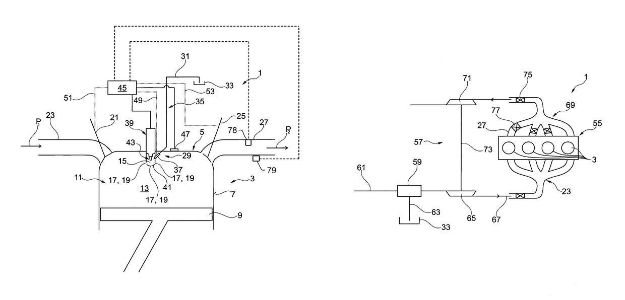
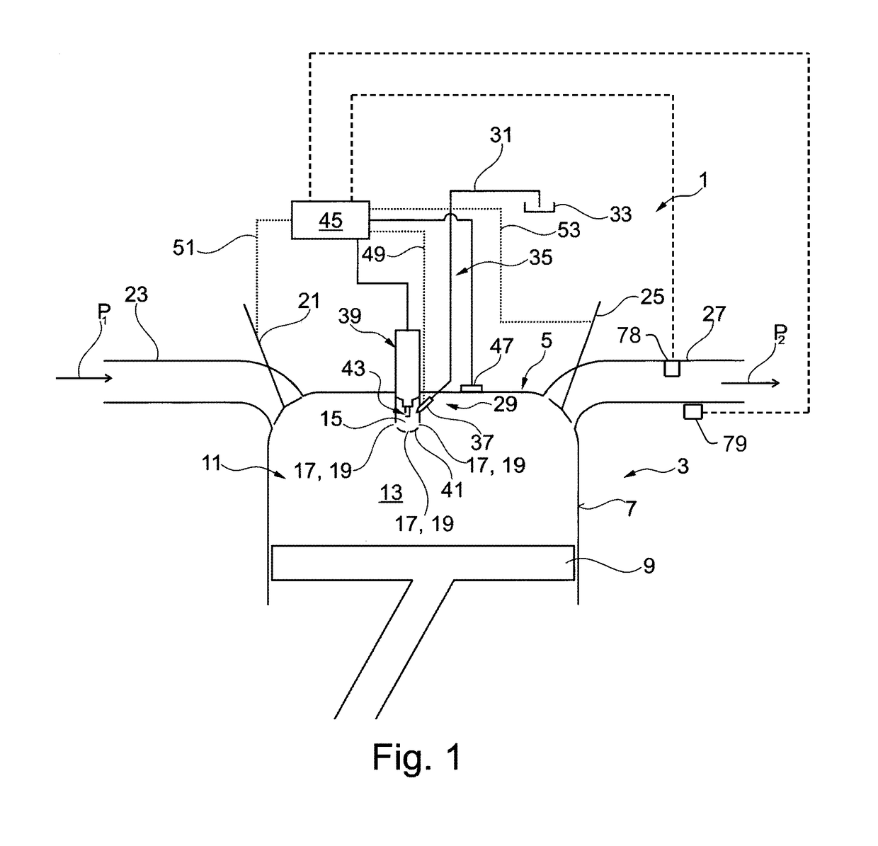
[0036]Referring now to the drawings, and more particularly to FIG. 1, a schematic partial detailed view of an embodiment of a mixture charged gas engine 1 is shown that includes at least one cylinder 3, wherein a combustion chamber 11, delimited by a cylinder head 5, a cylinder wall 7 and a piston 9 that is arranged movably in cylinder 3, is arranged in cylinder 3.

[0037]Combustion chamber 11 is divided into a main combustion chamber 13 and a pre-chamber 15, wherein pre-chamber 15 is fluidically connected via an opening 17 with main combustion chamber 13. In FIG. 1, three openings 17 in the embodiment of firing channels 19 are shown. Pre-chamber 15 is therefore connected with main combustion chamber 13 through a plurality of firing channels 19.

[0038]In an intake stroke of piston 9 an air- / combustion gas mixture—as symbolized herein by an arrow P1—is admitted via an inlet valve 21 into main combustion chamber 13. For this purpose, a mixture line 23 can be provided through which the mi...


PUM


Abstract

A mixture-charged gas engine includes at least one cylinder. A combustion chamber delimited by a cylinder head, a cylinder wall, and a piston, which can be moved in the cylinder, is arranged in the at least one cylinder, and the combustion chamber is divided into a main combustion chamber and at least one pre-chamber fluidically connected to the main combustion chamber via at least one firing channel. An air- / combustion gas mixture can be supplied to the main combustion chamber via an inlet valve during an intake stroke of the piston. The mixture-charged gas engine is characterized in that a separate combustion gas supply is provided for the at least one pre-chamber.

Description

CROSS REFERENCE TO RELATED APPLICATIONS[0001]This is a continuation of PCT application No. PCT / EP2013 / 003313, entitled “MIXTURE-CHARGED GAS ENGINE AND METHOD FOR COMPENSATING FOR VOLUMETRIC EFFICIENCY DEVIATIONS IN A MIXTURE-CHARGED GAS ENGINE”, filed Nov. 4, 2013, which is incorporated herein by reference.BACKGROUND OF THE INVENTION[0002]1. Field of the Invention[0003]The invention relates to a mixture charged gas engine, and to a method for compensating for volumetric efficiency deviations.[0004]2. Description of the Related Art[0005]Gas engines of the type discussed herein are known. It is hereby differentiated between pressurized or air charged gas engines on the one hand and mixture charged gas engines on the other hand. Both types of gas engines comprise at least one cylinder, wherein a combustion chamber, delimited by a cylinder head, a cylinder wall and a piston that can be moved in the cylinder is arranged in the at least one cylinder. The cylinder wall can herein also be t...

Claims


Application Information

Patent Timeline
Patent Type & Authority Patents(United States)
IPC IPC(8): F02B33/44F01N3/00F01N5/04F02B19/14F02B37/00F02B19/10F02B19/00F01N13/10F02B19/12
CPCF02B19/108F02B37/00F01N13/10F02B19/12F02B19/14F02B19/1085F02B43/00F02D41/0027F02D41/008F02M21/0284Y02T10/12Y02T10/30
Inventor ERNST, ANKOSANDER, UDO
Owner MOTOREN UND TURBINEN UNION MUNCHEN GMBH
Learn More