Speaker diaphragm, speaker, device, and method for manufacturing speaker diaphragm
a technology for speaker diaphragms and diaphragms, which is applied in the direction of loudspeaker diaphragm shapes, electrical transducers, electrical apparatus, etc., can solve the problems of difficult to reproduce low pitch sound, the support force of the suspension is reduced, and the function of video audio devices, so-called audio-visual equipment, are rapidly becoming more complex and the effect of reducing the supporting for
- Summary
- Abstract
- Description
- Claims
- Application Information
AI Technical Summary
Benefits of technology
Problems solved by technology
Method used
Image
Examples
first embodiment
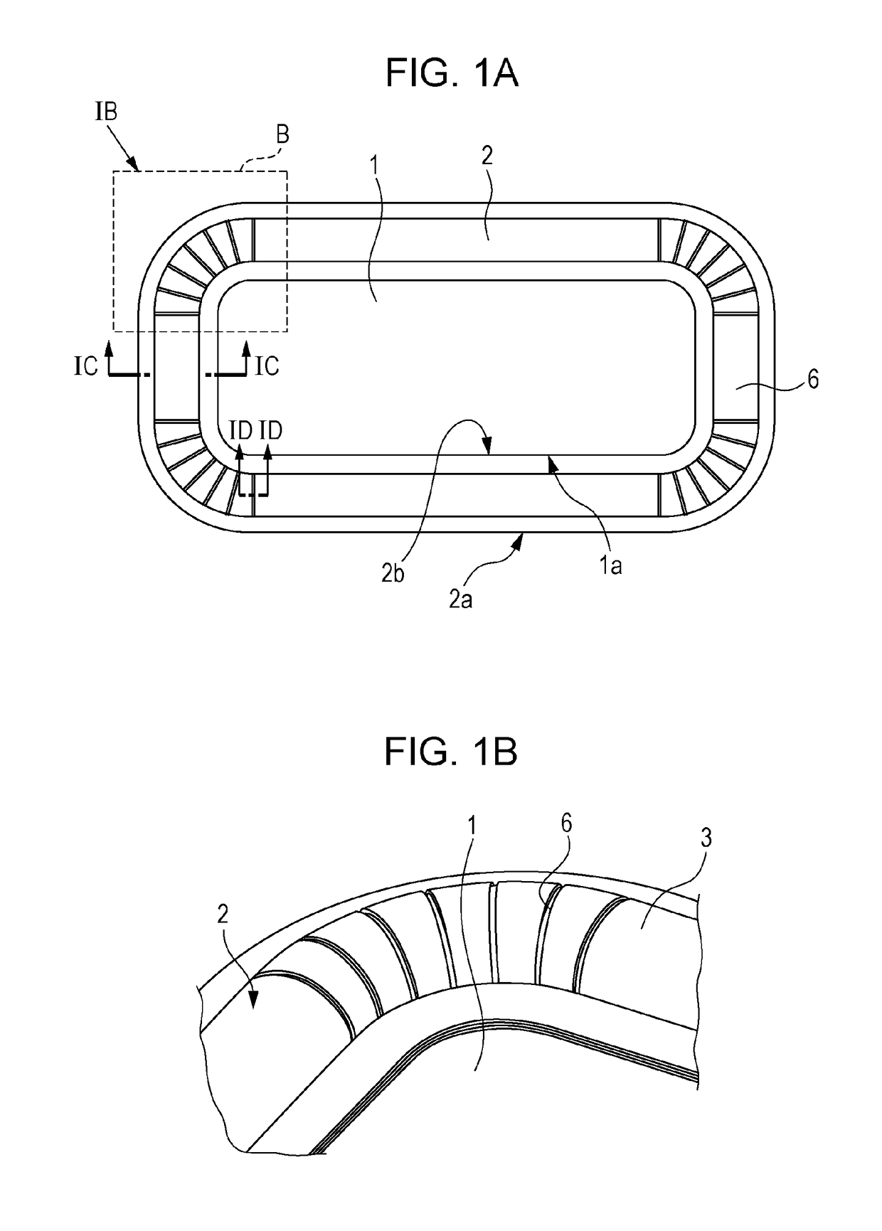
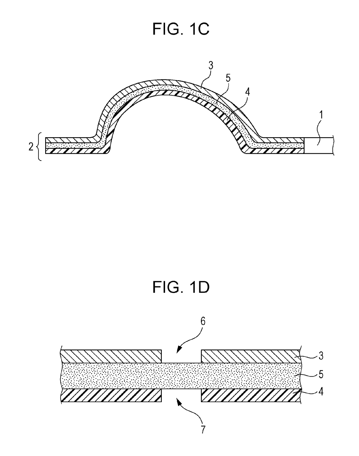
[0116]FIG. 1A is a top view of a speaker diaphragm according to the First Embodiment of the present disclosure. FIG. 1B is a perspective view for explaining a structure of the part IB indicated by the dotted line in FIG. 1A. FIG. 1C is a cross-sectional view taken along the line IC-IC in FIG. 1A. FIG. 1D is a cross-sectional view taken along the line ID-ID in FIG. 1A.
Configuration of Speaker Diaphragm
[0117]First, an example of a configuration of a speaker diaphragm according to the First Embodiment of the present disclosure is described. The speaker diaphragm according to the First Embodiment illustrated in FIGS. 1A through 1D includes a vibrator 1 (also referred to as a diaphragm 1) and a suspension 2.
[0118]The vibrator 1 has an outer peripheral part 1a that has, for example, a circular shape, an elliptic shape, a polygonal shape, or a shape combining two or more straight lines and two or more curves. For example, the outer peripheral part 1a has a so-called running track shape con...
application example
[0133]Some application examples using the speaker diaphragm according to the First Embodiment described above are described with reference to FIGS. 3A through 3E.
[0134]FIG. 3A illustrates a structure in which a sealing member 9 is provided so as to cover the first holes 6 of the top surface member 3. In a case where a speaker is mounted on a cabinet, a force according to acoustic compliance of the cabinet sometimes works on the suspension 2 during driving of the speaker. Furthermore, the intermediate member 5 is subject to repeated stresses in accordance with opening and closing of the first holes 6 and the second holes 7 caused by vibration of the vibrator 1. The configuration of this application example is for reinforcing the intermediate member 5 by using the sealing member 9 so that the intermediate member 5 has sufficient strength against the stresses.
[0135]According to this structure, the sealing member 9 is provided so as to fill the first holes 6. That is, the sealing member...
second embodiment
[0139]FIG. 4A is a top view of a speaker diaphragm according to the Second Embodiment of the present disclosure. FIG. 4B is a perspective view for explaining a structure of the part IVB indicated by the dotted line in FIG. 4A. FIG. 4C is a cross-sectional view taken along the line IVC-IVC in FIG. 4A. FIG. 4D is a cross-sectional view taken along the line IVD-IVD in FIG. 4A.
Configuration of Speaker Diaphragm
[0140]First, the configuration of the speaker diaphragm according to the Second Embodiment of the present disclosure is described. The speaker diaphragm according to the Second Embodiment illustrated in FIGS. 4A through 4D includes a vibrator 1, a suspension 2, and a sealing member 9.
[0141]The vibrator 1 has an outer peripheral part 1a that has, for example, a circular shape, an elliptic shape, a polygonal shape, or a shape combining two or more straight lines and two or more curves. The vibrator 1 illustrated in FIG. 4A has a substantially rectangular shape constituted by four st...
PUM
 Abstract
Description
Claims
Application Information
 - R&D
- Intellectual Property
- Life Sciences
- Materials
- Tech Scout
- Unparalleled Data Quality
- Higher Quality Content
- 60% Fewer Hallucinations
Browse by: Latest US Patents, China's latest patents, Technical Efficacy Thesaurus, Application Domain, Technology Topic, Popular Technical Reports.
© 2025 PatSnap. All rights reserved.Legal|Privacy policy|Modern Slavery Act Transparency Statement|Sitemap|About US| Contact US: help@patsnap.com


