
Humidity sensor, humidity sensing method and transistor therefor

a humidity sensor and humidity sensing technology, applied in the field of humidity sensors, can solve the problems of high reaction rate, large time required for detecting rapid change of humidity, signal distortion, etc., and achieve the effects of long recovery time, low response speed, and mass production

Active Publication Date: 2017-05-30
KOREA ADVANCED INST OF SCI & TECH
View PDF11 Cites 1 Cited by
  • Summary
  • Abstract
  • Description
  • Claims
  • Application Information

AI Technical Summary

Benefits of technology

The present invention is a new type of humidity sensor that addresses several issues associated with conventional humidity sensors, such as hysteresis, slow response speed, long recovery time, unstable characteristics under high temperature and high humidity conditions, poor contact between the metal and a humidity sensing film, and reliability degradation due to the deterioration of the humidity sensing film when a long time has lapsed. The present invention is made of materials used in the semiconductor process, which allows for mass production. By not using polymer in the manufacture of the humidity sensor, the process becomes easier, and high reliability and reproductivity are obtained. The present invention can accurately detect humidity in any medium and provides a humidity sensing method and a transistor for sensing humidity.

Problems solved by technology

However, regarding the conventional humidity sensor using the above-mentioned humidity sensing film, in a case where defects occur in manufacturing the humidity sensing film, a signal may be distorted due to the influence of a parasitic capacitance.
Moreover, since the polymer layer should absorb the moisture, the reaction rate is low.
Additionally, much time is required for detecting rapid change of the humidity.
Also, the polymer is vulnerable to organic solvent like alcohol, etc., and may have a problem in adhering to electrodes.
Besides, it is difficult to obtain stable characteristics under high temperature and high humidity conditions.

Method used


Image

  • Humidity sensor, humidity sensing method and transistor therefor
  • Humidity sensor, humidity sensing method and transistor therefor
  • Humidity sensor, humidity sensing method and transistor therefor

Examples


Embodiment Construction

[0027]Hereafter, an exemplary embodiment of the present invention will be described in detail with reference to the accompanying drawings. The shapes and sizes and the like of components of the drawings are exaggerated for clarity of the description. It is noted that the same reference numerals are used to denote the same elements throughout the drawings. In the following description of the present invention, the detailed description of known functions and configurations incorporated herein is omitted when it may make the subject matter of the present invention unclear.

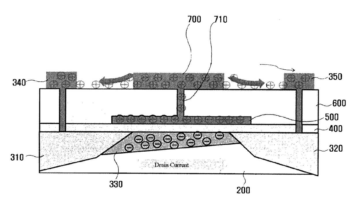
[0028]Unlike a conventional method, a humidity sensor and a humidity sensing method according to the present invention use an electric charge relaxation effect in which electric charges charged in a conductive material such as metal disappear into the surface of material in contact with the metal with the lapse of time.

[0029]FIG. 1 shows a basic structure of a humidity sensor and a humidity sensing method according to...


PUM

PropertyMeasurementUnit
timeaaaaaaaaaa
timeaaaaaaaaaa
timeaaaaaaaaaa

Abstract

Disclosed is a humidity sensor including: a conductive material in which electric charges are charged; a charger which charges the electric charges in the conductive material; and a measurer which measures a change amount of the electric charges charged in the conductive material.

Description

[0001]This application is the National Phase of PCT / KR2012 / 001138, filed Feb. 15, 2012, which claims priority to Korean Application No. 10-2011-0032135, filed Apr. 7, 2011, the disclosures of which are hereby incorporated by reference in their entirety.TECHNICAL FIELD[0002]The present invention relates to a humidity sensor, a humidity sensing method and a transistor for the same.BACKGROUND ART[0003]A humidity sensor may be applied to a variety of industries in the form of being used individually or together with sensors that obtain other kinds of information. The humidity sensor may be applied to logistics services, transport services and traffic network, etc., thereby enhancing services related thereto. Also, the humidity sensor may be applied to history management, production management, plant management and environment network construction of agriculture, fisheries, livestock industry, distribution industry and manufacturing industry and the like, and may be also applied to smart...

Claims


Application Information

Patent Timeline
Patent Type & Authority Patents(United States)
IPC IPC(8): G01N27/04G01N27/414
CPCG01N27/048G01N27/4141G01N27/22
Inventor YOON, JUN BOYANG, HYUN HOSONG, SEOK HO
Owner KOREA ADVANCED INST OF SCI & TECH
Learn More