
Method and apparatus to extend the effective dynamic range of an image sensing device

a technology of image sensing device and effective dynamic range, which is applied in the field of image capture, can solve the problems of correspondence problems, image sensing device dynamic range is very limited, and image quality of images obtained by image sensing device is reduced

Inactive Publication Date: 2005-06-21
OMNIVISION TECH INC
View PDF16 Cites 40 Cited by
  • Summary
  • Abstract
  • Description
  • Claims
  • Application Information

AI Technical Summary

Benefits of technology

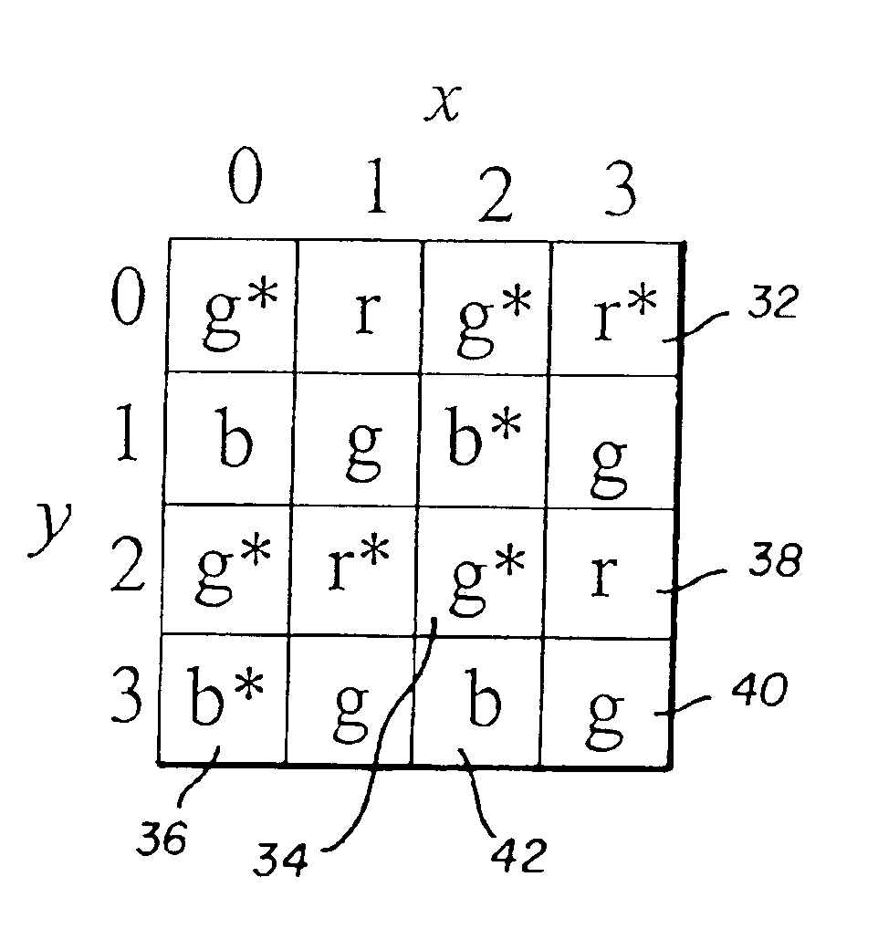
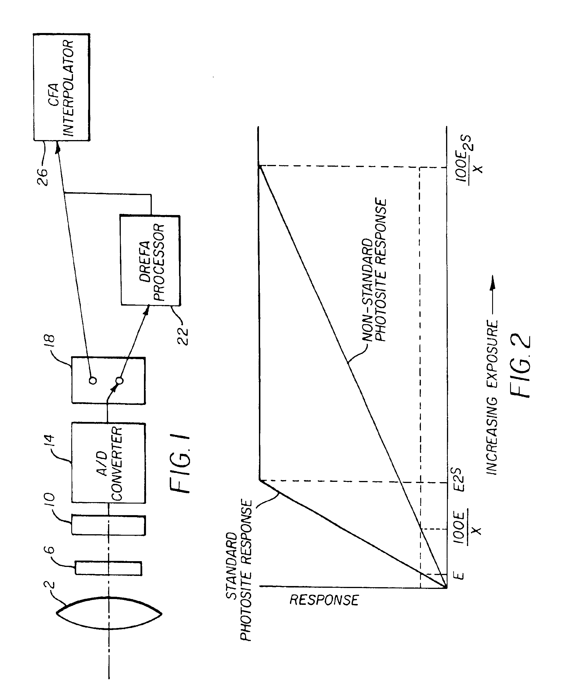
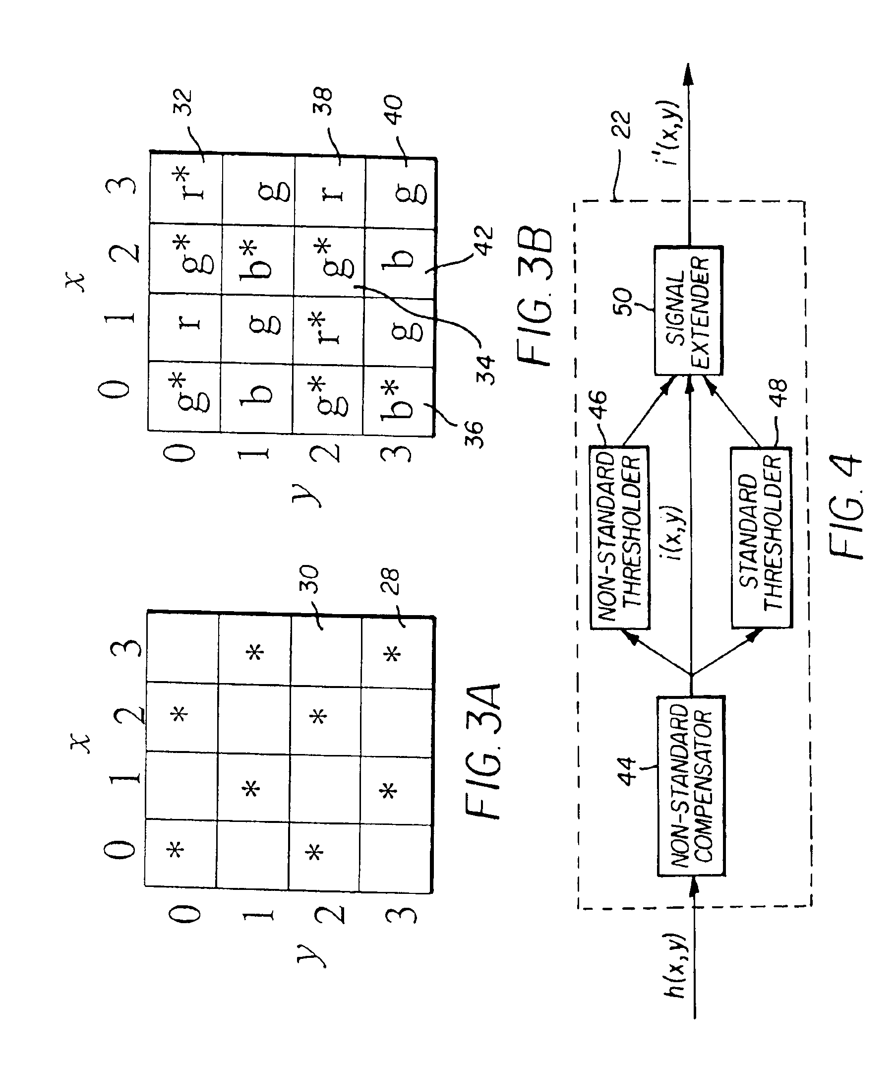
The present invention is about improving image capture by using a sensor with standard and non-standard photosites. The non-standard photosites have a slower response to light exposure, but the invention expands their response range to increased or decreased light exposures by utilizing the image signals from neighboring standard photosites. This results in an extended effective dynamic range of the image capture system. The image sensor can include a structural element, such as lenslets, mask, or neutral density filter, to enhance the non-standard photosites. The invention takes advantage of the dynamic ranges of all photosites to produce an image signal with increased dynamic range.

Problems solved by technology

These image sensing devices have a very limited dynamic range when compared to traditional negative film products.
Thus, the inferior dynamic range of an image sensing device relative to silver halide media results in lower image quality for images obtained by an image sensing device.
However, these prior art methods, including Ikeda, require multiple image signals to form an image signal having extended dynamic range.
Attaining such multiple signals can cause difficulty.
For example, if the multiple image signals are not captured simultaneously, objects moving in the scene or motion of the camera may produce artifacts in an image signal having extended dynamic range.
Additionally, if the image signals are captured simultaneously but on separate image capture devices, then a correspondence problem exists.
Moreover, the additional hardware adds undesirable cost to the imaging system.

Method used


Image

  • Method and apparatus to extend the effective dynamic range of an image sensing device
  • Method and apparatus to extend the effective dynamic range of an image sensing device
  • Method and apparatus to extend the effective dynamic range of an image sensing device

Examples


Embodiment Construction

[0019]Because imaging devices employing electronic sensors are well known, the present description will be directed in particular to elements forming part of, or cooperating more directly with, apparatus in accordance with the present invention. Elements not specifically shown or described herein may be selected from those known in the art. Note that as used herein, the term image is a two dimensional array of values. An image may be a two dimensional subset of another image.

[0020]Referring to FIG. 1, light from an object or scene is incident upon a lens 2. An optical low pass filter 6 performs a slight blurring of the image in order to reduce the occurrence of aliasing. The image falls on an image sensing device 10 such as a charged-coupled device (CCD). Note that other devices, such as CMOS devices, may be used as the image sensing device 10.

[0021]An A / D converter 14 converts the image signal from the image sensing device 10 into a digital signal. More specifically, the A / D conver...


PUM


Abstract

An image capture system generates an extended effective dynamic range from a signal provided by an image sensor by utilizing an image sensing device having standard photosites with a predetermined response to a light exposure and non-standard photosites with a slower response to the same light exposure. An optical section exposes the image sensing device to image light, thereby causing the image sensing device to generate an image signal and a processing section expands the response of the standard photosites to increased light exposures by utilizing the image signals from neighboring non-standard photosites. Furthermore, the processing section may expand the response of the non-standard photosites to decreased light exposures by utilizing the image signals from neighboring standard photosites. The differential response of the image sensor is provided by a structural element, such as an array of lenslets, a mask or a neutral density filter, overlying the photosites and providing the standard photosites with a predetermined standard response to a light exposure and the non-standard photosites with a slower response to the same light exposure.

Description

FIELD OF THE INVENTION[0001]The invention relates generally to the field of image capture, and more specifically to a method of extending the effective dynamic range of an image sensing device.BACKGROUND OF THE INVENTION[0002]Image sensing devices, such as a charge-coupled device (CCD), are commonly found in such products as digital cameras, scanners, and video cameras. These image sensing devices have a very limited dynamic range when compared to traditional negative film products. A typical image sensing device has a dynamic range of about 5 stops. This means that the exposure for a typical scene must be determined with a fair amount of accuracy in order to avoid clipping the signal. In addition, oftentimes the scene has a very wide dynamic range as a result of multiple illuminants (e.g. frontlit and backlit portions of a scene). In the case of a wide dynamic range scene, choosing an appropriate exposure for the subject often necessitates clipping data in another part of the image...

Claims


Application Information

Patent Timeline
Patent Type & Authority Patents(United States)
IPC IPC(8): H04N9/04H04N3/15H04N23/12H04N25/00
CPCH04N9/045H04N3/155H04N25/585H04N23/843H04N25/134
Inventor GALLAGHER, ANDREW C.NICHOLS, DAVID N.
Owner OMNIVISION TECH INC
Learn More