Process for natural gas liquefaction

a technology of natural gas and liquefaction, which is applied in the direction of liquefaction, gaseous fuels, lighting and heating apparatus, etc., to achieve the effect of high availability and equivalent thermodynamic performan

Active Publication Date: 2017-05-23
KEPPEL OFFSHORE & MARINE TECH CENT PTE LTD
View PDF33 Cites 5 Cited by
  • Summary
  • Abstract
  • Description
  • Claims
  • Application Information

AI Technical Summary

Benefits of technology

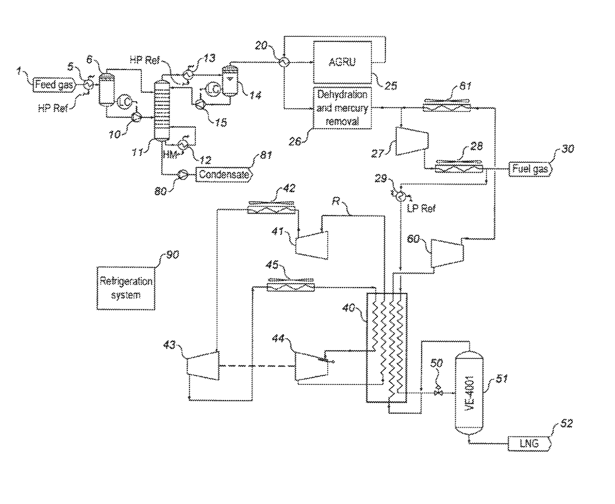
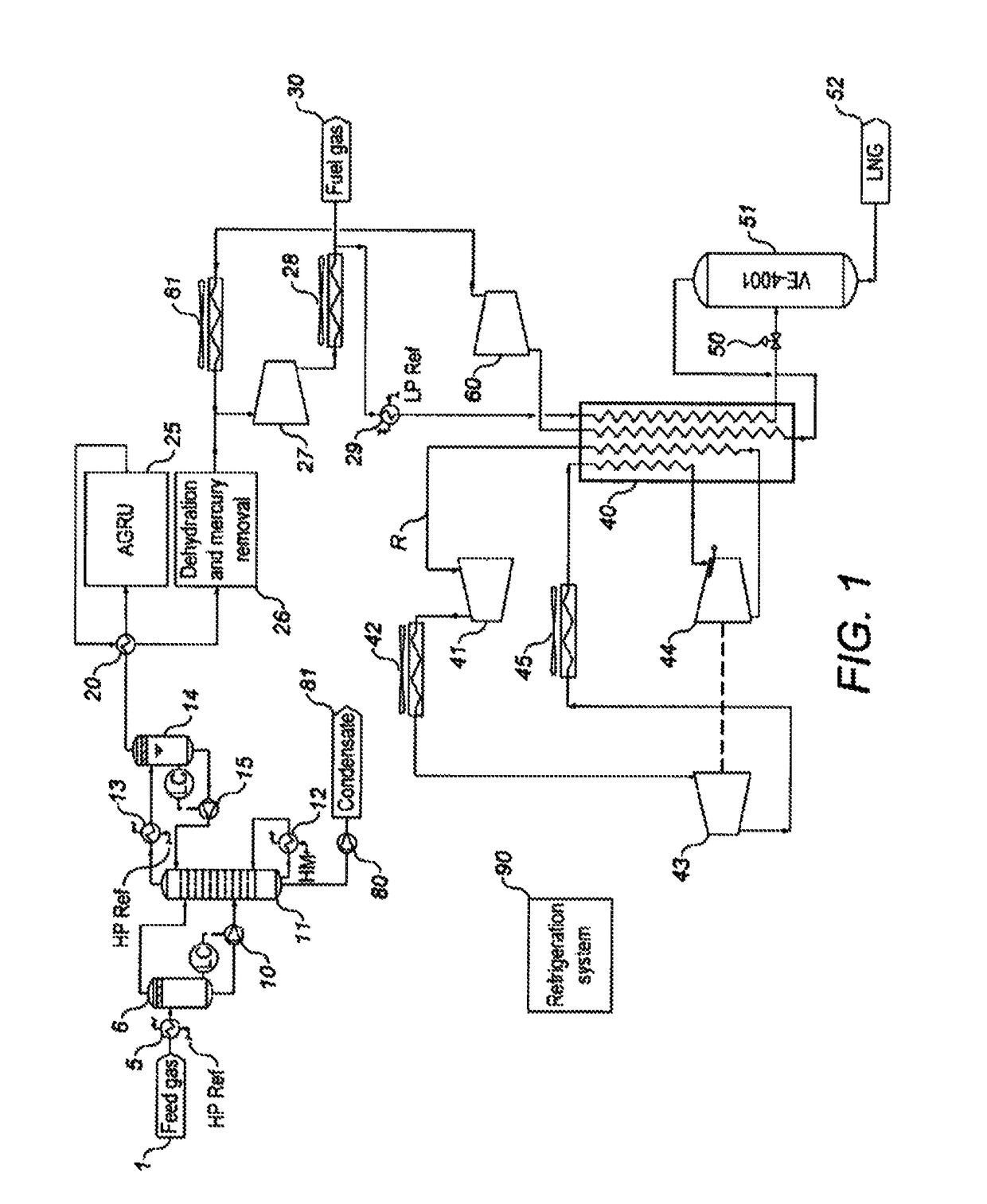
[0053]The present invention minimises the NGL extraction on the FPSO (floating production and storage offloading vessel) board, which makes the overall process simpler and safer. Only one fractionation column, i.e. scrub column, is needed to extract the condensate and BTX (i.e. benzene, toluene, and xylene). The scrub column can be located before the feed gas treatment (i.e. sweetening, dehydration, and Hg removal) so that dehydration of the raw condensate which is separated from the three phase separator is not necessary before it is fed into the scrub column.
[0054]The process according to the present invention is readily operable through the use of fewer columns not adapted for offshore applications and by using operations which are familiar to crude oil operators.
[0056]The process of the present invention is inherently safe through the use of safe, non-flammable refrigerants and through the minimisation of LPG processing and the minimisation of the total amount of equipment required, in particular the amount of cold equipment required.
[0058]The present invention is ideally suited for associated gas processing, and has the advantage of robustness, simplicity, highly available design with equivalent thermodynamic performance and inherent safety.

Problems solved by technology

In the case of associated gas, which is produced in association with oil production, there is no way to transport it to market in the absence of a pipeline.
This is costly and not always practical.
Offshore liquefaction of natural gas has not yet seen widespread implementation because of a few fundamental limitations.
One of the first challenges to the liquefaction of associated gas is developing a liquefaction process and transportation system that meets the requirements of the gas producers.
However, because the prior art has tended to focus on adapting the existing on-shore concepts to offshore liquefaction, there remain several limitations of the prior art when applied to associated gas processing.
The limitations of the prior art when applied to associated gas processing are:Process availability has been based on onshore LNG schemes that tend to focus on single trains of large compressors that must all be running to produce LNG;Prioritising process efficiency at the expense of operability by developing dual expander and mixed refrigerant processes adapted to attempt to preserve efficiency expected at large scale onshore LNG plants, which increases the process complexity;Inherent safety has typically been compromised by hydrocarbon inventories within mixed refrigerant processes but also by the amount of cryogenic processing equipment, and the operator's unfamiliarity with extensive cryogenic processing;Prior processes have failed to recognise and address the implication that personnel working in crude oil production and processing may not be familiar with cryogenic processes, equipment, or storage.
Process availability is critical for associated gas producers because an unavailable plant means that either crude oil production is decreased or the gas is flared whilst the plant is down.
Adopting on-shore large-scale LNG processes has resulted in minimum redundancy and acceptance of a resultant loss in availability when one of the large compressor sets is down.
Operability is another limitation of many of the processes developed for offshore liquefaction.
Some highly efficient onshore processes derived from mixed refrigerant and dual mixed refrigerant processes offer very good thermodynamic performance but at the cost of decreased inherent safety, increased process complexity, and decreased operability.
However, the complexity of the mixed refrigerant greatly influences the offshore operation and safety issues.
The process efficiency is improved by mixing with the nitrogen small amounts of hydrocarbons, though the inherent safety is compromised.
The cascade arrangement of the process limits the LNG process in large scale applications.
However, all the above offshore LNG production processes focus on relatively large scale (>1 MTPA) processes and the feed gas is mainly stranded gas from the gas field.
However, little attention is paid to the rich associated gas which serves as the feed gas of an offshore LNG plant.

Method used


Image

  • Process for natural gas liquefaction
  • Process for natural gas liquefaction
  • Process for natural gas liquefaction

Examples


example 1

[0107]In accordance with the present invention, use of the vapour compression cycle refrigerant, in conjunction with a single N2 expander cycle greatly reduces the total duty by more than 13 MW. Furthermore the compressor duty for the nitrogen compressors of this Example is actually smaller than the dual N2 expander cycle of Comparative Example 2. This indicates the small CAPEX need for the plant as the gas turbine is a big cost in the total CAPEX.

example 2

[0108]Use of the vapour compression cycle refrigerant in conjunction with a dual N2 expander cycle results in an even greater reduction in compressor duty. Although the duty is 2 MW less than for Example 1, the same model of gas turbine is still needed, which indicates no cost saving on the gas turbine but greater CAPEX on the second turboexpander.

[0109]It is obvious that the present invention is advantageous in terms of the overall process efficiency (with an overall thermal efficiency of 91.13%) and CAPEX.

[0110]

TABLE 1Performance comparison of different natural gas liquefaction cyclesVapourcompressioncyclecompressorN2For 80dutycompressormmscfddriven byduty drivenN2of feedTotalelectricalby gascompressorassociatedCompressormotorturbinegas turbinegasduty (MW)(MW)(MW)selectionComparative37037LM6000,Example 1Comparative27027PGT25+,Example 2RB211-6762Example 123.74.619.1PGT25,RB211-6556,Titan 250Example 221.74.617.1PGT25,RB211-6556,Titan 250


PUM

PropertyMeasurementUnit
absolute pressureaaaaaaaaaa
temperatureaaaaaaaaaa
absolute pressureaaaaaaaaaa

Abstract

A natural gas liquefaction process suited for offshore liquefaction of natural gas produced in association with oil production is described.

Description

FIELD OF THE INVENTION[0001]The present invention relates to a natural gas liquefaction process, and particularly relates to an offshore apparatus for liquefying natural gas associated with oil production.BACKGROUND OF THE INVENTION[0002]This invention relates to a method for offshore production of liquefied natural gas (LNG), wherein the gas is supplied from an underground reservoir as either associated or non-associated gas. In the case of associated gas, which is produced in association with oil production, there is no way to transport it to market in the absence of a pipeline. This gas has often historically been flared. More recent aspirations to decrease the environmental consequences of producing oil have increasingly led to the gas being re-injected into underground reservoirs. This is costly and not always practical. Liquefaction of this gas offers a way to transport this gas to market by reducing the gas volume in the liquid phase at low temperatures.[0003]Increasingly, li...

Claims


Application Information

Patent Timeline
Patent Type & Authority Patents(United States)
IPC IPC(8): F25J1/00F25J3/02F25J1/02C10L3/10
CPCC10L3/102C10L3/10F25J1/004F25J1/005F25J1/0022F25J1/0042F25J1/0072F25J1/0097F25J1/021F25J1/023F25J1/0205F25J1/0238F25J1/0248F25J1/0278F25J1/0283F25J1/0284F25J1/0288F25J1/0289F25J1/0294F25J3/0209F25J3/0233F25J3/0238F25J3/0242F25J3/0247F25J2200/74F25J2215/62F25J2220/60F25J2220/62F25J2220/64F25J2230/22F25J2230/60F25J2240/40F25J2270/90F25J2290/72F25B9/006F25J1/0211
Inventor BARCLAY, MICHAELCAMPBELL, PAULSHENG, XIAOXIACHONG, WEN SIN
Owner KEPPEL OFFSHORE & MARINE TECH CENT PTE LTD
Why Eureka
Try Eureka