Eureka AIR delivers breakthrough ideas for toughest innovation challenges, trusted by R&D personnel around the world.

Resonant converter and controlling method thereof

a technology of resonant converter and controlling method, which is applied in the direction of process and machine control, electrical energy, instruments, etc., can solve the problems of easy execution of methods, high current damage to resonant converters, and crucial overcurrent protection

Active Publication Date: 2017-05-16
FSP POWERLAND TECH +1
View PDF4 Cites 2 Cited by
  • Summary
  • Abstract
  • Description
  • Claims
  • Application Information

AI Technical Summary

Benefits of technology

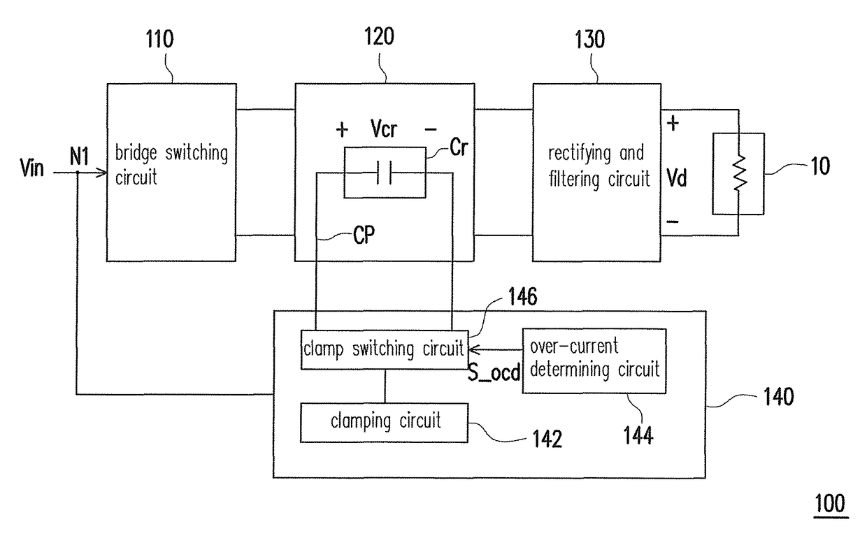
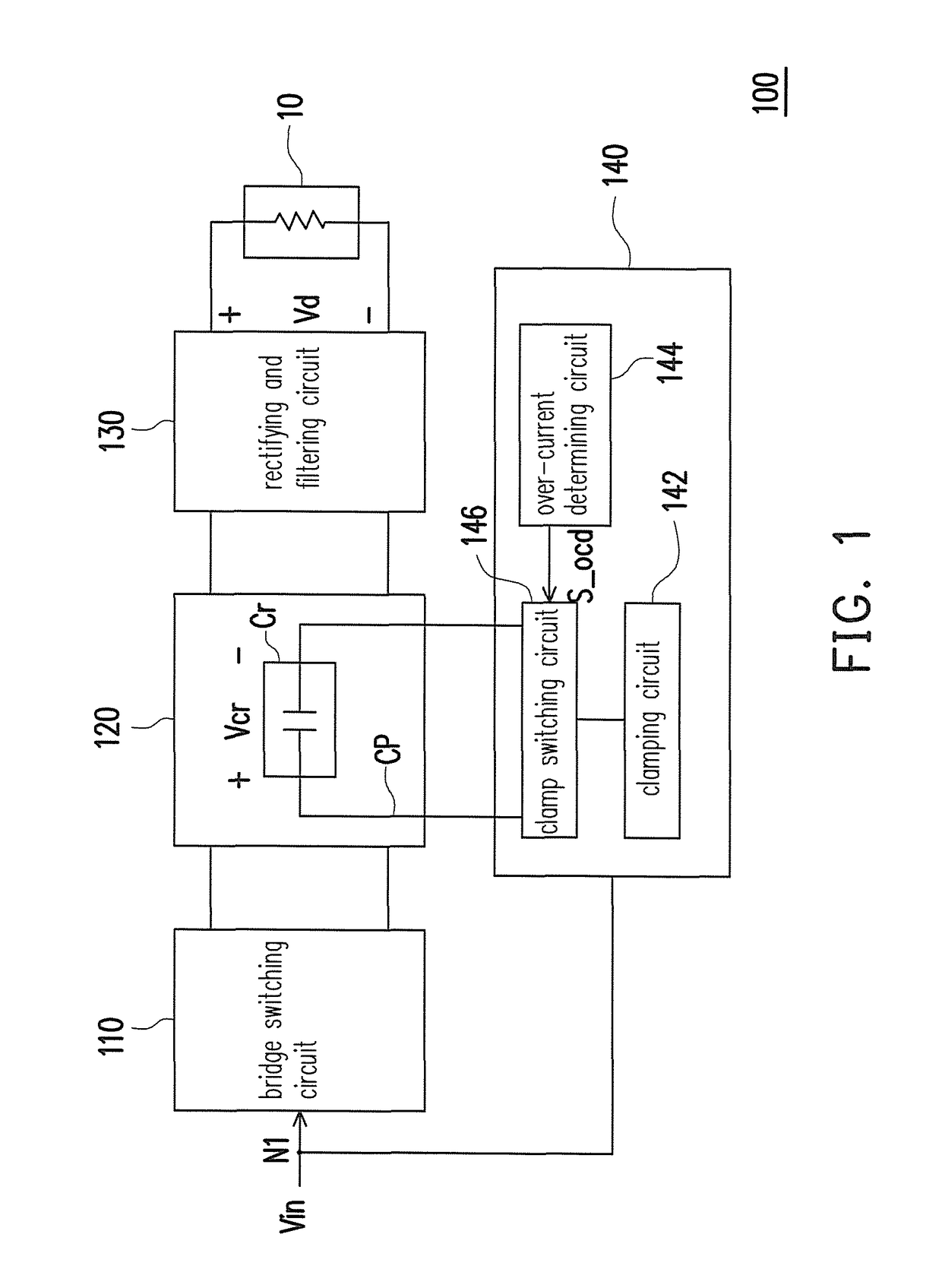
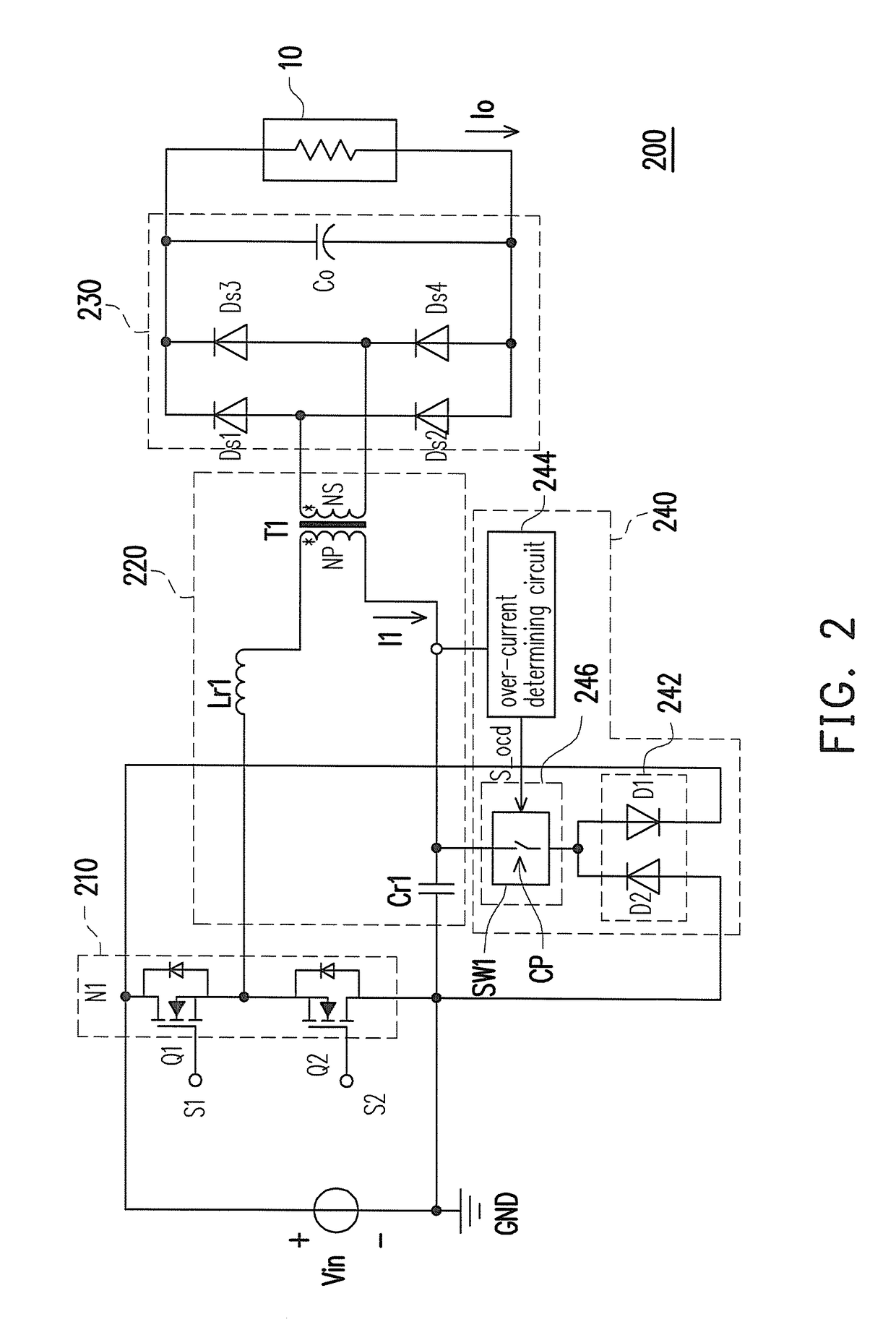
[0031]In view of the above, a resonant converter and a controlling method thereof are provided herein. The resonant converter may determine whether the over-current phenomenon occurs at the load by detecting the current on its primary winding or the load. The resonant converter conducts the clamp path to provide the over-current protection if the over-current phenomenon occurs at the load, and cuts off the clamp path to exempt the resonant capacitance from being limited by the DC input voltage when the over-current phenomenon does not occur at the load. Therefore, the resonant converter may be free of extra limitation in terms of determination the circuit parameters and the operation range, and the difficult and costs of overall circuit design may be further reduced.

Problems solved by technology

As to the circuit design of resonant converters, the over-current protection is a crucial issue.
If the resonant current is not limited or protected, the resonant converter is very much likely to be damaged by high current.
The foregoing method is easy to execute, and periodic current limitation may be achieved without configuring any additional control circuit, which is powerless control.
Hence, the design of the resonant circuit has some limits, and the operation range of the resonant circuit may be affected.
In addition, when the resonant converter goes into the hold up time, since the cross voltage of the resonant capacitor is limited by the clamping diode, the stored energy of the resonant circuit may be decreased and thus decreasing the maximum gain of the output voltage.
As a result, designers may have to use large capacitors to comply with the requirement of the hold up time, and problems regarding the increase in size and costs of the resonant converter may occur.

Method used


Image

  • Resonant converter and controlling method thereof
  • Resonant converter and controlling method thereof
  • Resonant converter and controlling method thereof

Examples


Embodiment Construction

[0039]An embodiment of the invention provides a resonant converter and a controlling method thereof. The resonant converter may determine whether the over-current phenomenon occurs at a load by detecting a current on its primary winding or the load. The resonant converter conducts a clamp path to provide the over-current protection when the over-current phenomenon occurs at the load, and the resonant converter cuts off the clamp path to exempt the resonant capacitance from being limited by a DC input voltage when the over-current phenomenon does not occur at the load. Therefore, the resonant converter may be free from extra limitation in terms of determination the circuit parameters and the operation range, and the difficulty and costs of overall circuit design may be further reduced. In order to make the disclosure more comprehensible, embodiments are described below as examples showing that the disclosure can be actually realized. The embodiments provided herein are only for an il...


PUM


Abstract

A resonant converter and its controlling method are provided. The resonant converter includes a bridge switching circuit receiving a DC input voltage through its power terminal, a resonant and transforming circuit, a rectifying and filtering circuit, and an over-current protecting circuit. The resonant and transforming circuit has at least one resonant capacitor charged / discharged in response to the switching of the bridge switching circuit. The rectifying and filtering circuit rectifies and filters outputs of the resonant and transforming circuit, and generates a driving voltage accordingly. The over-current protecting circuit is coupled to the power terminal and crosses over the resonant capacitor to form a clamp path. The over-current protecting circuit detects a current flowing through the resonant and transforming circuit or a load and determines whether to conduct / cut off the clamp path according to the detection result to limit a cross voltage of the resonant capacitor within a first voltage range.

Description

CROSS-REFERENCE TO RELATED APPLICATION[0001]This application claims the priority benefit of China application serial no. 201310353646.3, filed on Aug. 15, 2013. The entirety of the above-mentioned patent application is hereby incorporated by reference herein and made a part of this specification.BACKGROUND OF THE INVENTION[0002]Field of Invention[0003]The invention relates to a power converting technique and more particularly to a resonant converter and a controlling method thereof.[0004]Description of Related Art[0005]The development trend of direct current (DC) converters, similar to that of most power supply products, is toward high efficiency, high power density, high reliability, and low costs. Since resonant converters (e.g., LLC resonant converters, etc.) are capable of performing zero-voltage switching (ZVS) in the primary winding and zero-current switching (ZCS) in the secondary winding on the full-load range, the resonant converters have gradually been applied as DC conver...

Claims


Application Information

Patent Timeline
Patent Type & Authority Patents(United States)
IPC IPC(8): H02M3/335H02M1/32H02M1/00
CPCH02M1/32H02M3/33569H02M2001/0058Y02B70/1433Y02B70/1491Y02P80/112H02M1/0058H02M3/33573H02M3/33571H02M3/01Y02B70/10Y02P80/10
Inventor XU, MINGDUAN, FEI-YUE
Owner FSP POWERLAND TECH
Why Eureka
Eureka Blog
Learn More