
Sensor circuit and semiconductor device including sensor circuit

a sensor circuit and semiconductor technology, applied in the field of semiconductor devices, can solve the problems of increasing the manufacturing cost of the sensor circuit, affecting the accuracy of the measurement results, and the degradation of the photodiode, and achieve the effects of high reliability, high sensitivity to ultraviolet light, and high reliability of the semiconductor

Active Publication Date: 2017-05-09
SEMICON ENERGY LAB CO LTD
View PDF125 Cites 0 Cited by
  • Summary
  • Abstract
  • Description
  • Claims
  • Application Information

AI Technical Summary

Benefits of technology

[0009]In addition, the photodiode using silicon has relatively high sensitivity to visible light in many cases. To increase the sensitivity to ultraviolet light, the structure of the photodiode is devised; for example, a filter that selectively transmits ultraviolet light is provided; the thickness of a silicon film is adjusted; or the position of an impurity region is controlled. Unfortunately, each structure is a factor in increasing the manufacturing cost of the sensor circuit that enables to measure the doses of ultraviolet light.
[0011]Another object of one embodiment of the present invention is to provide a semiconductor device that can be used in a wide temperature range. Another object of one embodiment of the present invention is to provide a highly reliable semiconductor device. Another object of one embodiment of the present invention is to provide a high-performance semiconductor device.
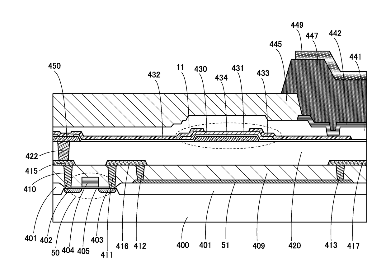
[0013]In a sensor circuit using an oxide semiconductor that has a larger band gap than silicon, the absorption edge of light can be on a shorter wavelength side than that in a sensor circuit using silicon. Specifically, in the case where an IGZO-based oxide semiconductor having a band gap of approximately 3.2 eV is used for a sensor circuit, the absorption edge of light is approximately four hundreds and several tens of nanometers; thus, the sensitivity to ultraviolet light can be increased. The use of an oxide semiconductor having a higher band gap than silicon can also suppress an increase in dark current caused by a rise in sensor circuit temperature, which widens the temperature range where the sensor circuit can be used.
[0015]With the above structure, in one embodiment of the present invention, threshold voltage shift of the transistor including a channel formation region in an oxide semiconductor can be prevented; as a result, the reliability of the sensor circuit can be increased.
[0018]With one embodiment of the present invention, a sensor circuit that can be used in a wide temperature range, a highly reliable sensor circuit, or a sensor circuit having high sensitivity to ultraviolet light can be provided. In addition, with one embodiment of the present invention, a semiconductor device that can be used in a wide temperature range, a highly reliable semiconductor device, or a high-performance semiconductor device can be provided.

Problems solved by technology

The photodiode using silicon has another problem in that the photodiode is greatly degraded by continuous ultraviolet light irradiation and thus has low reliability.
Unfortunately, each structure is a factor in increasing the manufacturing cost of the sensor circuit that enables to measure the doses of ultraviolet light.

Method used


Image

  • Sensor circuit and semiconductor device including sensor circuit
  • Sensor circuit and semiconductor device including sensor circuit
  • Sensor circuit and semiconductor device including sensor circuit

Examples


Embodiment Construction

[0037]Embodiments of the present invention will be described below in detail with reference to the accompanying drawings. Note that the present invention is not limited to the following description, and it is easily understood by those skilled in the art that the mode and details can be variously changed without departing from the scope and spirit of the present invention. Accordingly, the present invention should not be construed as being limited to the description of the embodiments below.

[0038]Note that a sensor circuit of one embodiment of the present invention can be employed for a wide variety of semiconductor devices such as integrated circuits, RF tags, and semiconductor display devices. The semiconductor devices using a sensor circuit are included in the category of the present invention. The integrated circuits include, in its category, large scale integrated circuits (LSIs) including a microprocessor, an image processing circuit, a digital signal processor (DSP), and a mi...


PUM


Abstract

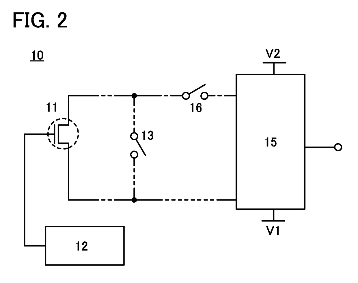
A sensor circuit includes a transistor comprising an oxide semiconductor; a first circuit which supplies one of a first potential and a second potential; a first switch; a second switch; and a second circuit to which a current flowing between a source and a drain of the transistor is applied via the second switch when the first potential is applied to a gate of the transistor. The first potential is lower than a potential of the source or a potential of the drain of the transistor, and the second potential is higher than the potential of the source or the potential of the drain of the transistor. The first switch electrically connects the source and the drain of the transistor when the second potential is applied to the gate of the transistor, and electrically isolates them when the first potential is applied to the gate of the transistor.

Description

BACKGROUND OF THE INVENTION[0001]1. Field of the Invention[0002]The present invention relates to a semiconductor device. For example, the present invention relates to a sensor circuit and a semiconductor device including the sensor circuit.[0003]2. Description of the Related Art[0004]The doses of ultraviolet light reaching the earth's surface are increasing. As a countermeasure against ultraviolet light, there is a movement to install a sensor circuit that enables to measure the doses of ultraviolet light in a portable electronic device. Installing a sensor circuit that enables to measure the doses of ultraviolet light in a portable electronic device can satisfy users' needs of measuring the doses of ultraviolet light in desired places.[0005]Patent Document 1 describes an ultraviolet light sensor using a silicon photodiode.REFERENCEPatent Document[0006][Patent Document 1] Japanese Published Patent Application No. 2007-067331SUMMARY OF THE INVENTION[0007]To install a sensor circuit t...

Claims


Application Information

Patent Timeline
Patent Type & Authority Patents(United States)
IPC IPC(8): H01L31/02H01L31/0296G01J1/42G01J1/02G01J1/44
CPCH01L31/0296G01J1/0219G01J1/429G01J1/44G01J2001/4473
Inventor KOYAMA, JUNYOKOI, TOMOKAZUMURAKAWA, TSUTOMU
Owner SEMICON ENERGY LAB CO LTD
Learn More