
LED signaling device for a bicycle

a signaling device and light-emitting diode technology, applied in the direction of anti-theft cycle devices, vehicle components, cycle equipment, etc., can solve the problems of reducing the safety of cyclists, and reducing so as to achieve sufficient response time and effectively reduce the chance of bicycle accidents

Active Publication Date: 2017-05-02
TENNUS IND
View PDF16 Cites 6 Cited by
  • Summary
  • Abstract
  • Description
  • Claims
  • Application Information

AI Technical Summary

Benefits of technology

The present invention is an LED signaling device for bicycles that can display multiple signaling messages to passersby and drivers of vehicles in the proximity of the bike. The device is mounted on the front or back of the bike and can be controlled by the cyclist through an operation interface. The LED array can generate specific signal symbols to warn passersby and drivers of the next move of the bike, which can help to lower the chance of bike accidents. The technical effects of this invention are that it provides a simple and effective way for cyclists to communicate with drivers and passersby, improving awareness and response time.

Problems solved by technology

However, just like any other transportation tools, the prevalence of bicycles brings forth escalating accident rate.
People realize that cycling may put cyclists under the threat of injury or death as a result of accidents.
However, the conventional lighting device can only alert passerby and vehicles ahead or in the nearby with rather limited signaling features, such as continuous lighting means or flashing lighting means.
For example, when cyclists are making a sudden left or right turn or are braking, adjacent passerby or transportation tools may ignore the messages from the cyclists and bring on a traffic accident.

Method used


Image

  • LED signaling device for a bicycle
  • LED signaling device for a bicycle
  • LED signaling device for a bicycle

Examples


Embodiment Construction

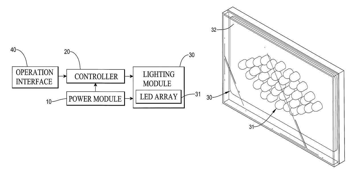
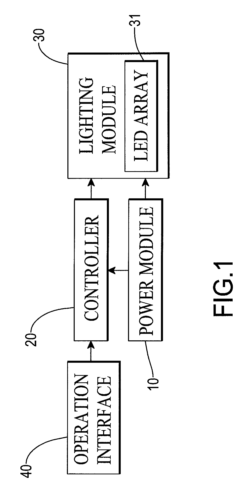
[0025]With reference to FIG. 1, a light emitting diode (LED) signaling device in accordance with the present invention has a power module 10, a controller 20, at least one lighting module 30 and an operation interface 40.

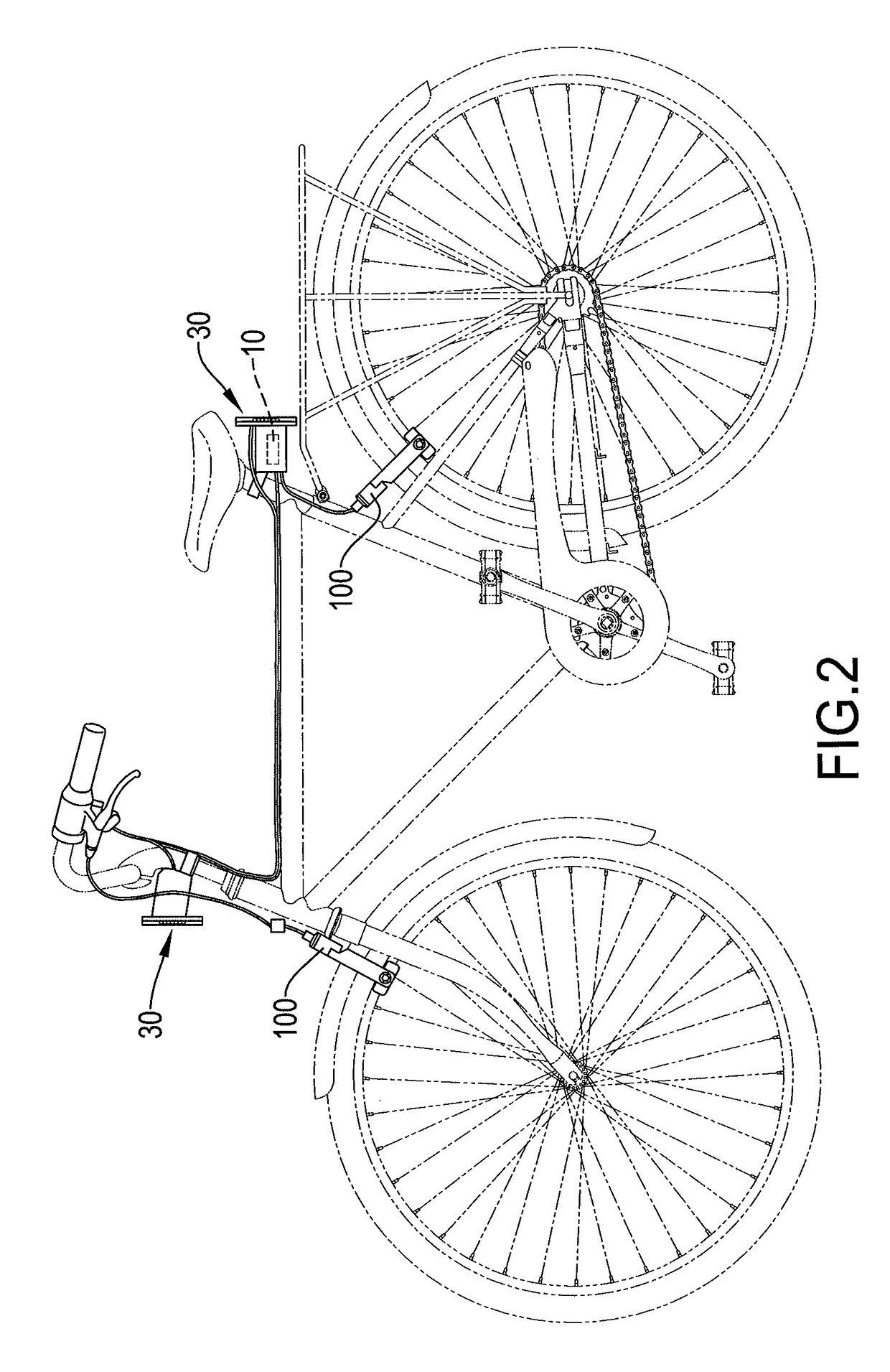
[0026]Each one of the at least one lighting module 30 has a light-emitting diode (LED) array 31 electrically connected to the controller 20 and the power module 10. The controller 20 is connected to the operation interface 40 and the power module 10 to control the LED array 31 of the lighting module 30 to turn on or turn off. With reference to FIG. 2, the power module 10 is mounted underneath a bike saddle of a bike, and may be an alkaline battery or a lithium battery for supplying or storing power.

[0027]With reference to FIGS. 2 and 3, there are two lighting modules 30 are respectively mounted on the front and the back of the bike. Specifically, one of the two lighting modules 30 is mounted on a handlebar of the bike to emit light toward a forward direction, and th...


PUM


Abstract

A bicycle LED signaling device for a bicycle includes a lighting module with at least one array of light emitting diodes (LEDs), a power source, an operation interface, and a controller connected to the power source and the operation interface to receive an operation command to control the LED array to display a corresponding signal.

Description

BACKGROUND OF THE INVENTION[0001]1. Field of the Invention[0002]The present invention relates to an LED (Light emitting diode) signaling device for a bicycle and, more particularly, to an LED signaling device mounted on a bicycle to alert passerby or transportation tools in front or back of the bicycle.[0003]2. Description of the Related Art[0004]Bicycles have become an increasingly popular mid-distance and short-distance transportation tool and an exercise tool lately because of the eco-friendly nature thereof. However, just like any other transportation tools, the prevalence of bicycles brings forth escalating accident rate. People realize that cycling may put cyclists under the threat of injury or death as a result of accidents. Therefore, many bike manufacturers start focusing on improvement for bike safety, such as front wheel and rear wheel brakes, material and weight of bike frame, passive reflector, active signaling and flashing indicators and the like, to enhance the safety...

Claims


Application Information

Patent Timeline
Patent Type & Authority Patents(United States)
IPC IPC(8): B60Q1/34B60Q1/44B62H5/20B62J6/04B62J6/00
CPCB62H5/20B62J6/005B62J6/04B62J6/16B62J6/045B62J6/056
Inventor LEE, CHING-CHIANG
Owner TENNUS IND
Learn More