
Switching circuit

a switching circuit and circuit technology, applied in the field of switching circuits, can solve problems such as deterioration of mixer operation, overlap, and corruption of fundamental signals

Active Publication Date: 2017-04-25
MEDIATEK SINGAPORE PTE LTD SINGAPORE
View PDF7 Cites 2 Cited by
  • Summary
  • Abstract
  • Description
  • Claims
  • Application Information

AI Technical Summary

Benefits of technology

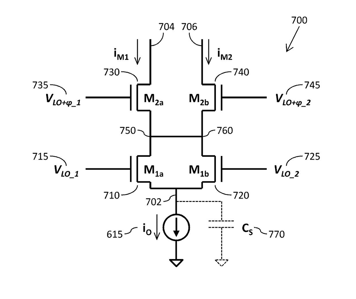
[0018]In this manner, and as described in greater detail below, by stacking two pairs of switching devices in this manner, and electrically coupling the common node between the first switching devices of each pair to the common node between the second switching devices of each pair, the effect of DSD products on the (wanted) fundamental output signal of the mixer is significantly reduced.

Problems solved by technology

Distortion introduced by the mixer may lead to corruption of the fundamental signal, and to unwanted spectral components at other frequencies that may cause involuntary interference to other transmitter units.
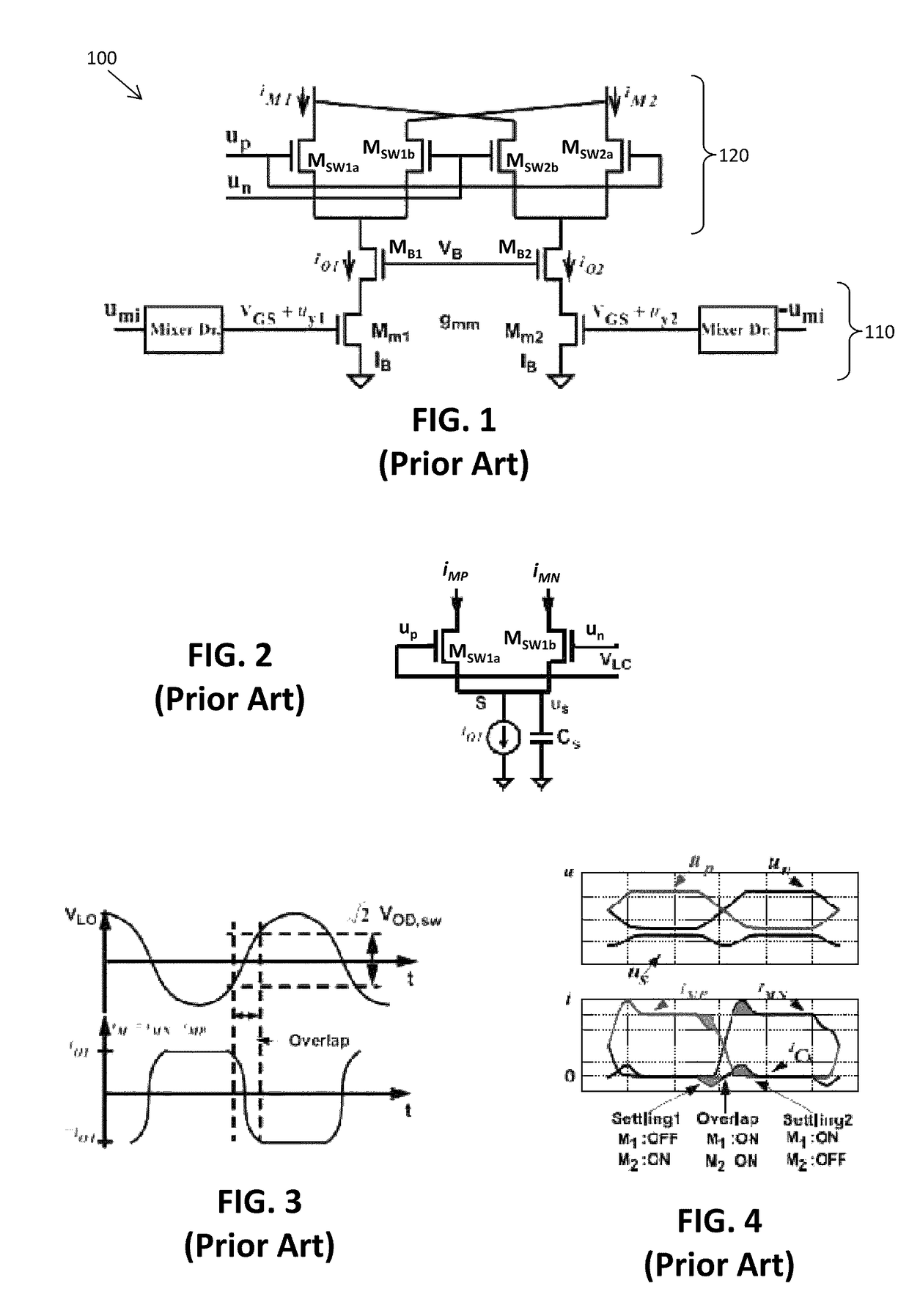
However, in practice the switching transistor devices Msw_1a,1b are not capable of switching instantaneously, resulting in periods of overlap when both switching transistor devices Msw_1a,1b within the pair are ‘on’ simultaneously.
However, a problem with this solution is in generating the quenching signals, which need to be very concise and timed correctly (the delay needs to be either close to zero, or carefully synchronised) so as to only affect the overlap period.
As long as the quenching devices are active, they will short circuit the mixer, and if they are on for longer than necessary it will noticeably deteriorate the mixer operation (reduced gain).
Generating such a quenching signal in practice is difficult, and the circuits used to generate such a signal would typically have high power consumption.

Method used


Image

  • Switching circuit
  • Switching circuit
  • Switching circuit

Examples


Embodiment Construction

[0060]According to examples of the present invention, there is provided a switching circuit for an active mixer. The switching circuit comprises a first pair of parallel switching devices and a second pair of parallel switching devices. The first and second pairs of parallel switching devices are arranged in a stacked configuration between an input node at which an input current comprising a first input frequency signal is received and a pair of differential output nodes. The first pair of switching devices are controlled by a second input frequency signal. The second pair of switching devices are controlled by a phase-shifted counterpart of the second input frequency signal. A common node between the first switching devices of the first and second pairs of switching devices is electrically coupled to a common node between the second switching devices of the first and second pairs of switching devices.

[0061]Advantageously, by stacking two pairs of switching devices in this manner, a...


PUM


Abstract

There is provided a switching circuit for an active mixer. The switching circuit comprises a first pair of parallel switching devices and a second pair of parallel switching devices. The first and second pairs of parallel switching devices are arranged in a stacked configuration between an input node at which an input current comprising a first input frequency signal is received and a pair of differential output nodes. The first pair of switching devices are controlled by a second input frequency signal. The second pair of switching devices are controlled by a phase-shifted counterpart of the second input frequency signal. A common node between the first switching devices of the first and second pairs of switching devices is electrically coupled to a common node between the second switching devices of the first and second pairs of switching devices.

Description

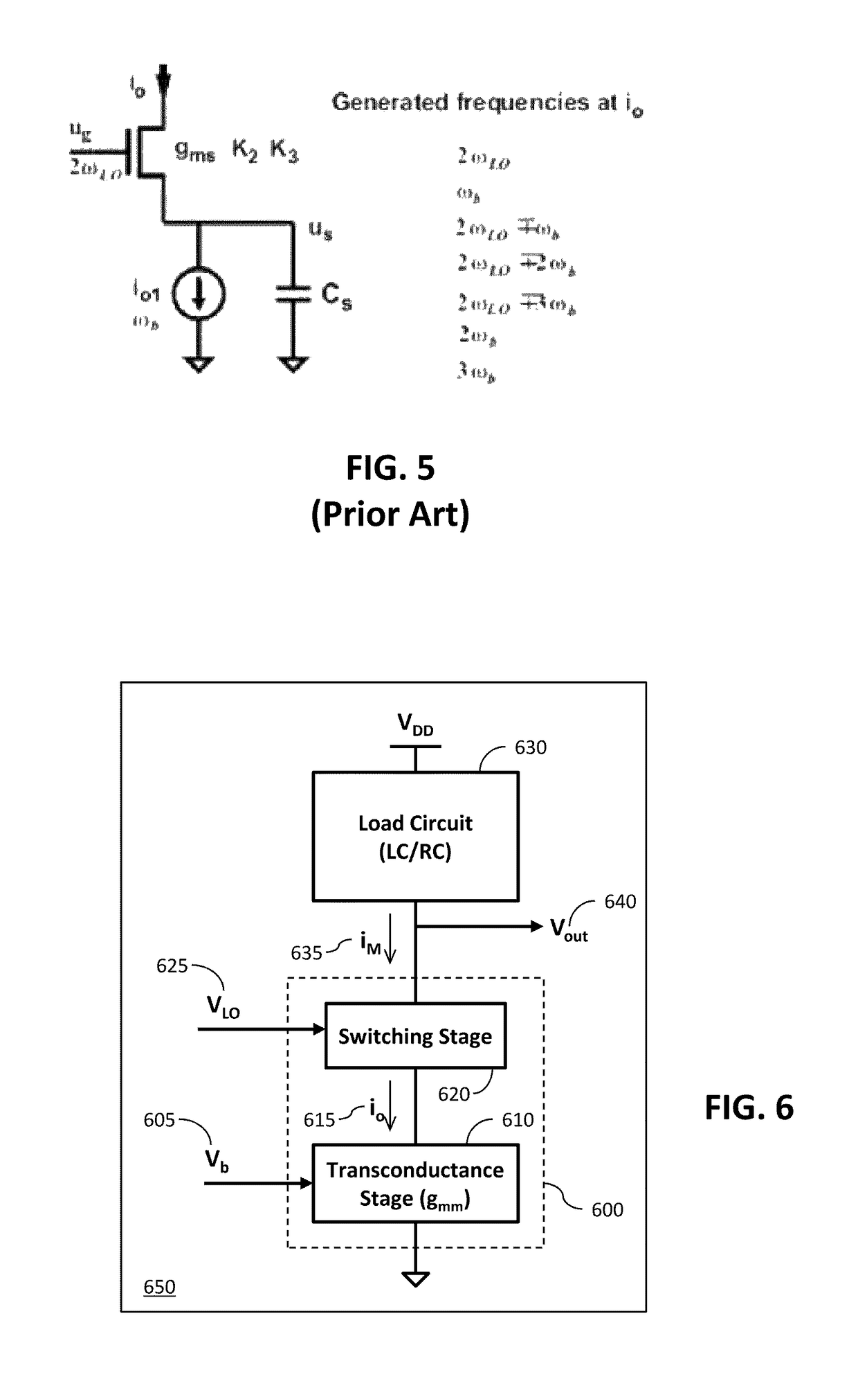
FIELD OF THE INVENTION[0001]This invention relates to a switching circuit, and in particular to a switching circuit for an active mixer.BACKGROUND OF THE INVENTION[0002]In the field of radio frequency (RF) transmitters, mixers are used to convert a low frequency baseband or intermediate frequency up to an RF frequency. Distortion introduced by the mixer may lead to corruption of the fundamental signal, and to unwanted spectral components at other frequencies that may cause involuntary interference to other transmitter units. It is therefore important to minimise the distortion introduced by the mixer.[0003]FIG. 1 illustrates an example of a conventional active mixer structure 100. Active mixers are capable of gain (unlike passive mixers) and use an amplifying device to ensure a required signal strength of the product signal. They also provide good isolation between the input and output ports. Specifically, FIG. 1 illustrates a double balanced mixer. Advantageously, a double balanced...

Claims


Application Information

Patent Timeline
Patent Type & Authority Patents(United States)
IPC IPC(8): H03D7/14H03D7/16H03K17/687
CPCH03D7/1441H03D7/1458H03D7/165H03K17/687
Inventor BRYANT, CARL
Owner MEDIATEK SINGAPORE PTE LTD SINGAPORE
Learn More