Eureka AIR delivers breakthrough ideas for toughest innovation challenges, trusted by R&D personnel around the world.

Pneumatic tire

a technology of pneumatic tires and pneumatic rims, which is applied in the field of pneumatic tires, can solve the problems of tire likely to be subjected to partial wear, and achieve the effects of reducing contact pressure, less susceptible, and improving the partial wear resistance of the tread

Active Publication Date: 2017-04-25
BRIDGESTONE CORP
View PDF30 Cites 2 Cited by
  • Summary
  • Abstract
  • Description
  • Claims
  • Application Information

AI Technical Summary

Benefits of technology

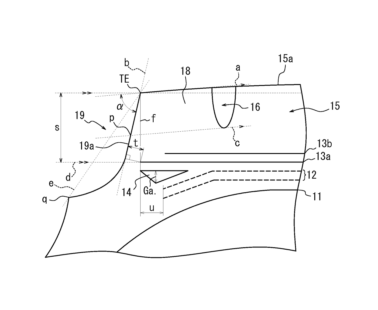
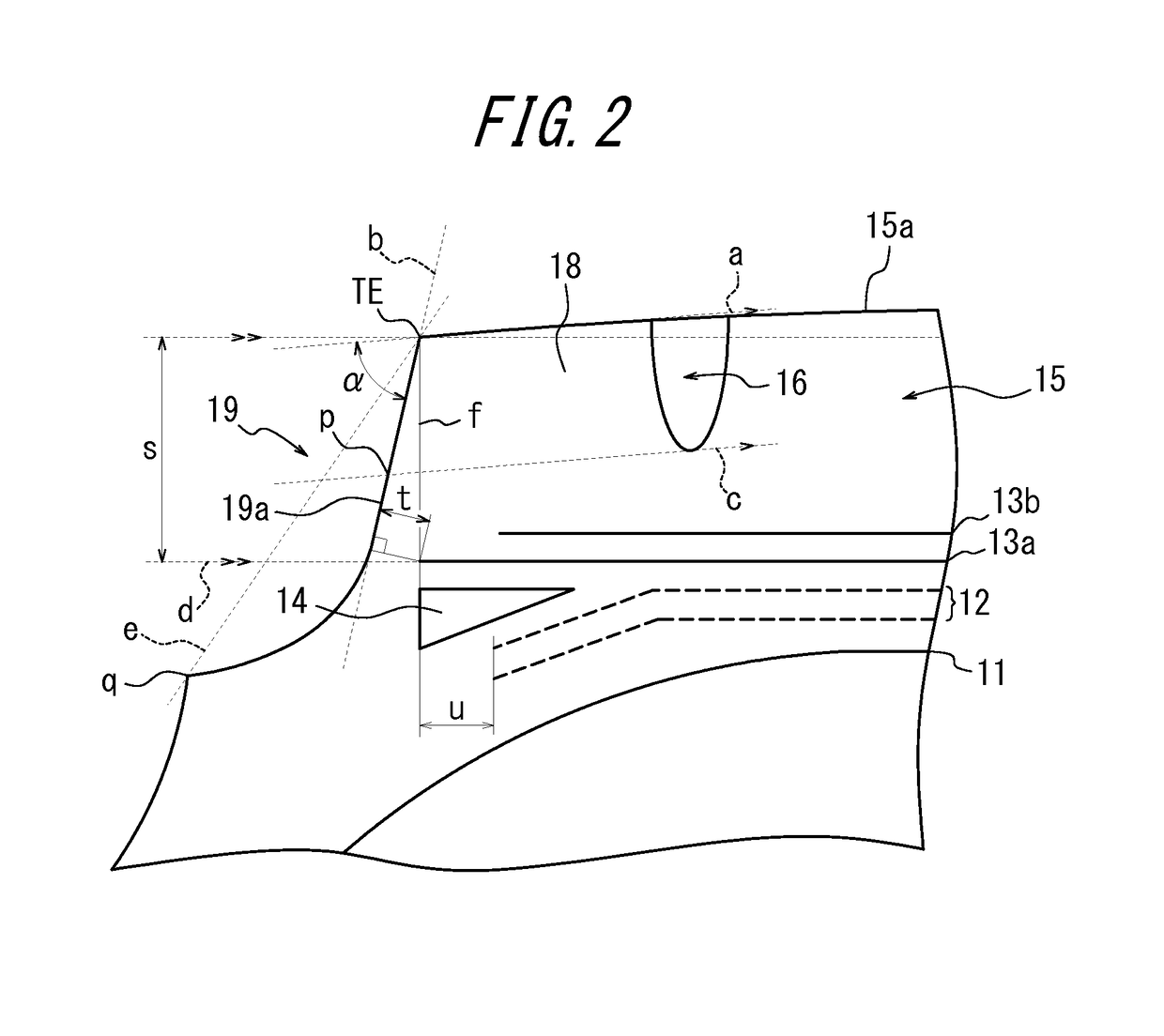
[0018]The pneumatic tire according to the present invention has a buttress portion disposed on the outside in the tire width direction of the tread and connects the tread surface to the sidewall, the buttress portion having an outer surface formed in a concave shape in section in the tire width direction with a depth shallow enough not to be set into the inside in the tire width direction from the outside end of the tread surface in the tire width direction, which allows for proper handling of a tread separation failure that otherwise occurs when the belt reinforcing layer is increased in width, and of the generation of partial wear resulting from side force (SF) imparted when the tire is mounted onto a steering shaft, and also allow the tire to be used until the tread is completely worn out.
[0019]Further, in a pneumatic tire according to another aspect of the present invention, the outer surface of the buttress portion is formed to be in a shape having an inclination angle of 75 degrees or larger and 90 degrees or smaller relative to the tread surface, in section in the tire width direction, which suppresses reduction in contact pressure at the tread end, making the tread less susceptible to partial wear, to thereby improve the partial wear resistance of the tread.
[0020]Furthermore, in a pneumatic tire according to another aspect of the present invention, the shortest distance between the inclined belt layer having a largest width among the inclined belt layers and the outer surface of the buttress portion is 10 mm or more and 20 mm or less, which makes it possible to ensure a rubber gauge of a required level at the belt end portion while reducing the compressive elasticity modulus.
[0021]Still further, in a pneumatic tire according to another aspect of the present invention, the shortest distance between the outside end in the tire width direction of the tread surface and a belt end portion of the belt reinforcing layer is 0 mm or more and 25 mm or less, which reduces the compressive elasticity modulus while ensuring the distance between the belt end portion of an inclined belt layer having a largest belt width and the outer surface of the buttress portion.
[0022]Further, in a pneumatic tire according to another aspect of the present invention, the belt reinforcing layer has, at the belt end portion thereof, an interlayer thickness of at least 3.0 mm, so that it is possible to prevent a large interlayer shear distortion which may likely to occur in the belt end portion of the belt reinforcing layer due to tire deformation caused when the tire is brought into contact with the ground under load in a case where the belt width of the belt reinforcing layer is larger than 70% of the tire width.

Problems solved by technology

Further, in the case of a pneumatic tire to be mounted onto a steering shaft, the tire is likely to be subjected partial wear caused in the shoulder end side of the tread by side force (SF) generated due to a slip angle imparted thereto.

Method used


Image

  • Pneumatic tire
  • Pneumatic tire
  • Pneumatic tire

Examples


example

[0067]Tires in a size of 355 / 50R22.5 for use in trucks and buses are each assembled to a rim in a size of 11.75×22.5 to be filled to an air pressure (internal pressure) of 900 kPa, and subjected, as Conventional Example, Comparative Example 1, Comparative Example 2, and Examples 1 to 8, to durability test and wear test under a normal load of about 39 kN at a drum speed of 65 km / h.

[0068]Here, Conventional Example, and Comparative Examples 1 and 2 each have a buttress portion defined by a straight line connecting the tread end TE and the boundary q with the sidewall 20, rather than in a concave shape, while Examples 1 to 8 each have a buttress portion in a concave shape, that is, in a shape in which the tread end TE and the boundary q with the sidewall 20 are connected to each other by a concave curve.

[0069]In the durability test, a driving distance was measured before the tread separation failure occurred. In the wear test, the amount of wear in the tread was measured after the tire ...


PUM


Abstract

Provided is a pneumatic tire including: a belt reinforcing layer (12) having an outside end portion in the tire width direction disposed outside in the tire width direction than a tire circumferential groove (16) disposed at the outermost side in the tire width direction, in which a buttress portion (19) being positioned on the outside of a tread (15) in the tire width direction and connecting a surface (15a) of the tread (15) to a sidewall (20) is formed to have, in section in the tire width direction, an outer surface in a concave shape with a depth shallow enough not to be set into the inside in the tire width direction from the outside end of the surface (15a) of the tread (15) in the tire width direction.

Description

CROSS REFERENCE TO RELATED APPLICATIONS[0001]This application is a National Stage of International Application No. PCT / JP2012 / 000918 filed Feb. 10, 2012, claiming priority based on Japanese Patent Application No. 2011-028933 filed Feb. 14, 2011.TECHNICAL FIELD[0002]The present invention relates to a pneumatic tire, and more particularly to a pneumatic tire including a circumferential direction belt layer and an angled belt layer disposed on the outside of the carcass layer in the tire radial direction, which is for use in a heavy duty vehicles such as trucks and buses.BACKGROUND ART[0003]There has been conventionally known a tire which includes at least one belt reinforcing layer disposed on the outer circumferential side of the crown region of a carcass which may be radially configured, the belt reinforcing layer being formed of, for example, a cord extending at an angle of 5° or less relative to the tread circumferential direction so as to extend substantially in the tread circumf...

Claims


Application Information

Patent Timeline
Patent Type & Authority Patents(United States)
IPC IPC(8): B60C11/01B60C9/18B60C9/22B60C9/28
CPCB60C9/18B60C9/185B60C9/22B60C9/28B60C11/01B60C2200/06B60C2011/013
Inventor MINOWA, HIDEAKI
Owner BRIDGESTONE CORP
Why Eureka
Eureka Blog
Learn More