Eureka AIR delivers breakthrough ideas for toughest innovation challenges, trusted by R&D personnel around the world.

Camera and Method for Focus Based Depth Reconstruction of Dynamic Scenes

Inactive Publication Date: 2013-01-10
MITSUBISHI ELECTRIC RES LAB INC
View PDF3 Cites 46 Cited by
  • Summary
  • Abstract
  • Description
  • Claims
  • Application Information

AI Technical Summary

Benefits of technology

The patent is about a system and method that allows a conventional video camera to capture images with both depth of field and range information. This makes it possible to create artistic effects like extending or reducing the depth of field, as well as perform post-acquisition digital refocusing. The system uses biases to accurately handle the image data and compensates for varying focal blur.

Problems solved by technology

Acquiring an accurate OF, in the presence of varying focal blur, is a challenging task.
Focal blur variations cause inherent biases in the estimation of optical flow.

Method used


Image

  • Camera and Method for Focus Based Depth Reconstruction of Dynamic Scenes
  • Camera and Method for Focus Based Depth Reconstruction of Dynamic Scenes
  • Camera and Method for Focus Based Depth Reconstruction of Dynamic Scenes

Examples


Embodiment Construction

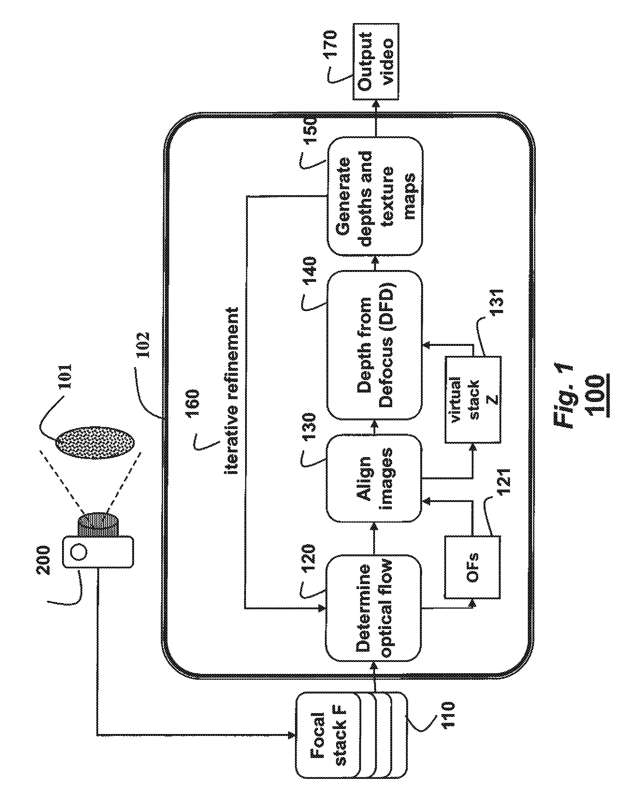
[0024]The embodiments of the invention provide a method for reconstructing a depth and extended depth of field video (EDOF) from a sequence of frames acquired by a video camera. The terms frame and image are used interchangeably herein.

[0025]DFD in Dynamic Scenes

[0026]We adapt conventional depth form defocus (DFD) methods to handle dynamic scenes, i.e., scenes with either camera or scene motion or both. Let us assume that we have the motion information between frame Fi and all the other frames within a focal stack F. Intuitively, this information can be used to warp frame {Fj}, for j=1 to M, to Fi.

[0027]This generates a virtual static focal stack Zi corresponding to the time instant i. Because the motion has been compensated for in the virtual static focal stack, the scene points are all in correspondence. Depth and texture maps for time instant i can then be obtained from our virtual static focal stack.

[0028]It is worth to note that no spatial or temporal information has been trade...


PUM


Abstract

A dynamic scene is reconstructed as depths and an extended depth of field video by first acquiring, with a camera including a lens and sensor, a focal stack of the dynamic scene while changing a focal depth. An optical flow between the frames of the focal stack is determined, and the frames are warped according to the optical flow to align the frames and to generate a virtual static focal stack. Finally, a depth map and a texture map for each virtual static focal stack is generated using a depth from defocus, wherein the texture map corresponds to an EDOF image.

Description

FIELD OF THE INVENTION[0001]This invention relates generally to video reconstruction, and more particularly to a camera and method for reconstructing depths and extended depth of field (EDOF) videos.BACKGROUND OF THE INVENTION[0002]Cameras are everywhere. There are billions of cell-phone cameras, over five hundred million surveillance cameras, cameras in cars, and at homes. In most cases, those cameras are passive devices that only record videos. This leaves most of the acquired videos unprocessed. A major bottleneck towards automating a visual scene interpretation is a lack of 3D information that is crucial for scene understanding. It is desired to adapt a conventional video camera to be able to provide meaningful 3D information during the acquisition of a video.[0003]Variable Focus Makes Cameras 3D[0004]Most modern cameras are equipped with features such as auto-focus, variable focal length and zoom, all of which require the focal distance to change. Unfortunately, this ability of...

Claims


Application Information

Patent Timeline
IPC IPC(8): H04N13/02
CPCG01B11/22H04N13/0271H04N5/2226H04N13/271
Inventor VEERARAGHAVAN, ASHOKSHROFF, NITESHTAGUCHI, YUICHITUZEL, CUNEYT ONCEL
Owner MITSUBISHI ELECTRIC RES LAB INC
Why Eureka
Eureka Blog
Learn More