
Implicit texture map parameterization for GPU rendering

a texture map and parameterization technology, applied in the field of processing, can solve the problems of difficult unwrapping of a mesh with arbitrary topology onto a continuous 2d rectangular texture domain, affecting the quality of the finished product, and introducing seam artifacts at the edges of each chart in the atlas, etc., to achieve good block-based texture compression and easy computation

Active Publication Date: 2017-04-18
ADVANCED MICRO DEVICES INC
View PDF33 Cites 1 Cited by
  • Summary
  • Abstract
  • Description
  • Claims
  • Application Information

AI Technical Summary

Benefits of technology

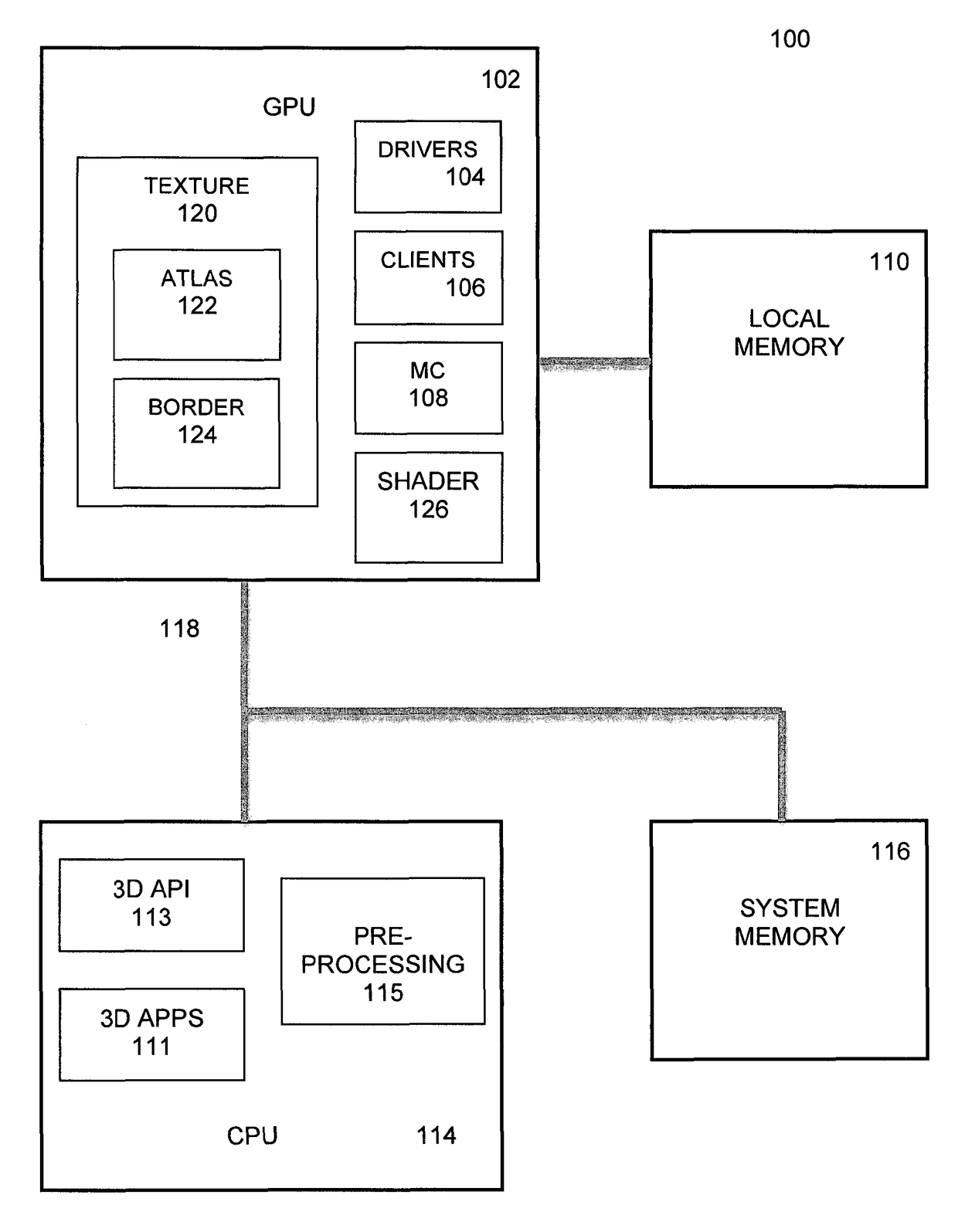
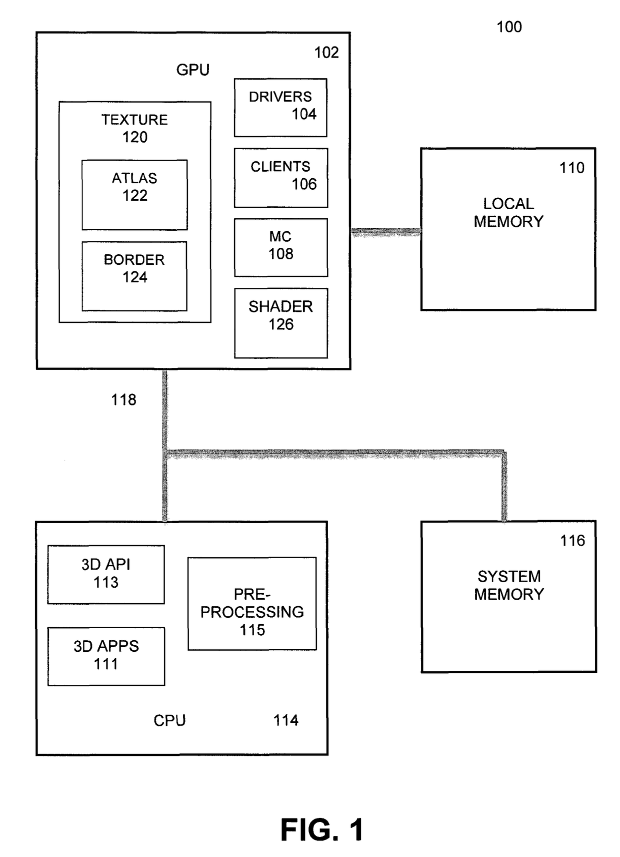
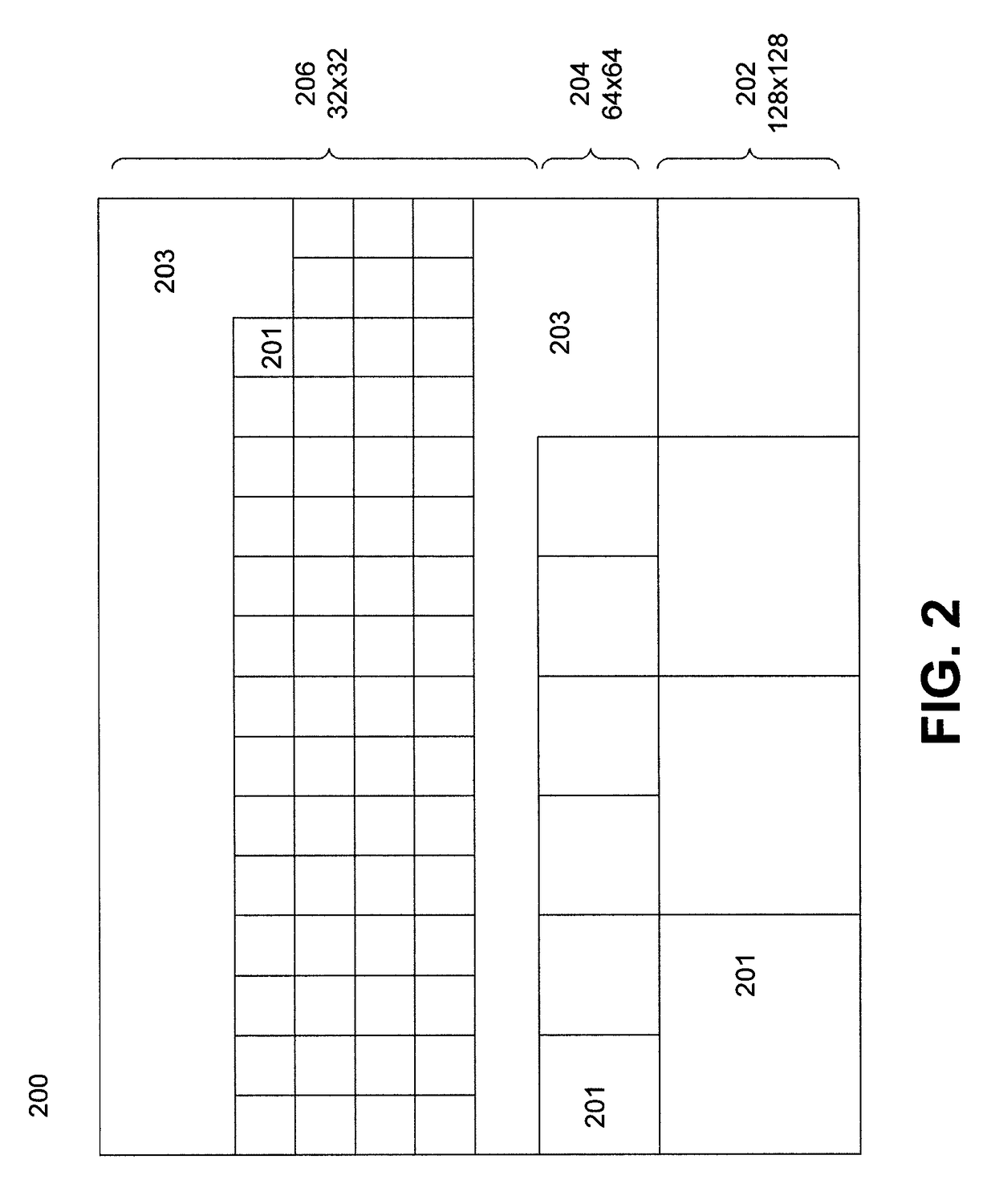
This patent describes a method for parameterizing textures in a way that takes advantage of existing methods for mapping textures onto models. The method packs all textures and their mip levels into a single texture atlas, which is organized by resolution. The textures are then laid out one after the other, making it easy to find the location of a particular texture within a resolution block. The method also includes borders and corners from adjacent faces to enable hardware filtering and compression of the textures. The "technical effect" of this patent is an improved method for texture mapping that makes it faster and more efficient.

Problems solved by technology

A fundamental texture authoring problem is that it is difficult to unwrap a mesh with arbitrary topology onto a continuous 2D rectangular texture domain.
Another problem associated with UV modeling is that edges of each chart in the atlas introduce seam artifacts.
This seam problem is especially pronounced when the texture is a displacement map used for hardware tessellation, as any discrepancy manifests as a crack in the surface.
Ptex, however, has certain drawbacks relative to conventional texture atlasing.
Significantly, Ptex is limited with regard to real time performance, in that it is typically not practical to have an individual texture for each primitive, and the indirection required when a filter kernel crosses from one face to another is costly in performance, and precludes the use of any hardware texture filtering.
The existing Ptex method does not address displacement mapping or texture compression, and other methods that involve displacement maps require manual fix-up or are restricted to simple models.

Method used


Image

  • Implicit texture map parameterization for GPU rendering
  • Implicit texture map parameterization for GPU rendering
  • Implicit texture map parameterization for GPU rendering

Examples


Embodiment Construction

[0007]Some embodiments are directed to a method and system for processing textures for a mesh comprising polygons for real-time rendering of an object or model in a processor, comprising associating an independent texture map with each face of the mesh to produce a plurality of face textures, packing the plurality of face textures into a single texture atlas, wherein the atlas is divided into a plurality of blocks based on a resolution of the face textures, adding a border to the texture map for each face comprising additional texels including at least border texels from an adjacent face texture map, and performing linear interpolation of a trilinear filtering operation on the face textures to resolve resolution discrepancies caused when crossing an edge of a polygon. These embodiments can also include a process that is configured to average texel values in the border to enable displacement mapping of the mesh.

[0008]Some embodiments are directed to an implicit texture parameterizati...


PUM


Abstract

Embodiments are described for a method for processing textures for a mesh comprising quadrilateral polygons for real-time rendering of an object or model in a graphics processing unit (GPU), comprising associating an independent texture map with each face of the mesh to produce a plurality of face textures, packing the plurality of face textures into a single texture atlas, wherein the atlas is divided into a plurality of blocks based on a resolution of the face textures, adding a border to the texture map for each face comprising additional texels including at least border texels from an adjacent face texture map, and performing linear interpolation of a trilinear filtering operation on the face textures to resolve resolution discrepancies caused when crossing an edge of a polygon.

Description

TECHNICAL FIELD[0001]One or more implementations relate generally to processors including graphical processing units, and more specifically to an efficient texture mapping process for rendering.BACKGROUND[0002]In computer graphics, texture mapping is a method for adding detail, surface texture, or color to a graphic object or 3D model. Texture filtering or smoothing is a method of determining the texture color for a texture mapped object using the colors of nearby texels (texture pixels) to allow a texture to be applied to many different shapes, sizes and angles while alleviating aliasing due to sampling artifacts.[0003]UV mapping is a common 3D modeling process of making a 2D image representation of a 3D model that projects a texture map onto a 3D object. The process involves assigning pixels in the image to surface mappings on the polygon, typically by copying triangular (or other polygon) faces of the image map onto corresponding polygons on the object. When a model is created as...

Claims


Application Information

Patent Timeline
IPC IPC(8): G06T15/04
CPCG06T15/04G06T2210/36
Inventor HILLESLAND, KARL E.HENSLEY, JUSTIN
Owner ADVANCED MICRO DEVICES INC
Learn More