
Data sampler circuit with equalization function and method for sampling data

a data sampler and equalization function technology, applied in the field of electronic circuits, can solve problems such as the decrease of the input sensitivity of the sampler

Active Publication Date: 2017-04-11
NXP USA INC
View PDF6 Cites 10 Cited by
  • Summary
  • Abstract
  • Description
  • Claims
  • Application Information

AI Technical Summary

Benefits of technology

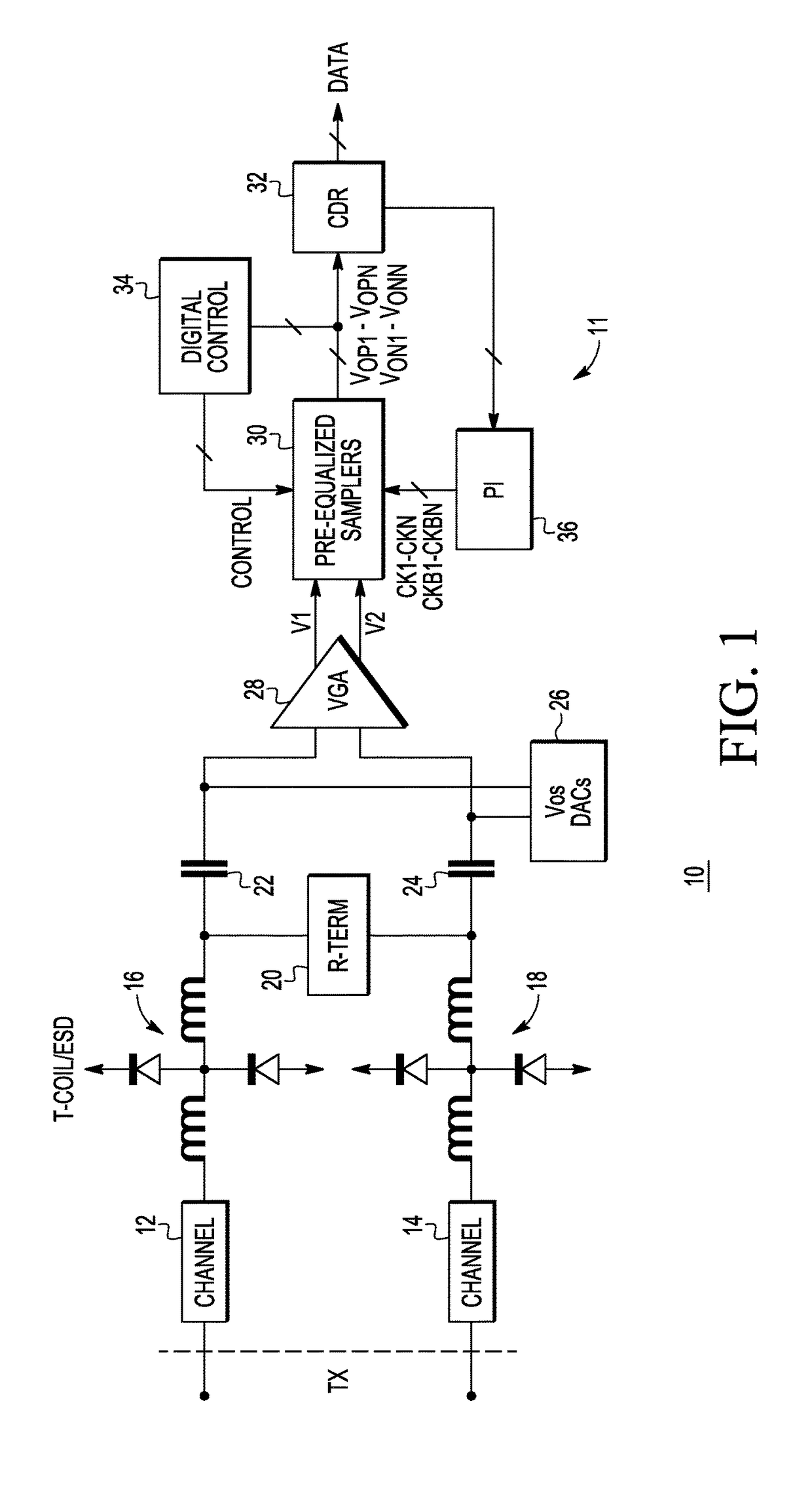
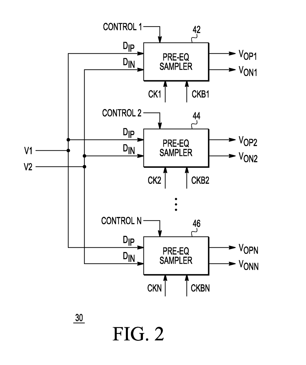
The patent text describes a new design for a sampler circuit that solves problems in previous designs. The new design includes a pre-equalizer that compensates for varying amplitudes due to channel loss or attenuation. The circuit also includes a negative resistance equalizing circuit that improves input sensitivity and compensates for high frequency gain response. The data sampler circuit is an analog operational circuit with current mode logic and differential signals. The circuit provides increased input sensitivity over conventional CMOS circuits. The technical effects of the new design include improved input sensitivity, compensation for varying amplitudes, and improved high frequency gain response.

Problems solved by technology

This may cause the input sensitivity of the sampler to decrease as clock frequency increases.

Method used


Image

  • Data sampler circuit with equalization function and method for sampling data
  • Data sampler circuit with equalization function and method for sampling data
  • Data sampler circuit with equalization function and method for sampling data

Examples


Embodiment Construction

[0010]Generally, there is provided, a receiver coupled to a transmitter through one or more channels. The receiver includes a plurality of data sampler circuits. Each of the data sampler circuits includes a transconductance amplifier, a latch circuit, a current-to-voltage converter, and a variable gain negative resistance equalizing circuit. The transconductance amplifier has an input and an output. The latch circuit is coupled to the output of the transconductance amplifier. The current-to-voltage converter has an input coupled to the output of the transconductance amplifier, and an output for providing a feedback signal to the latch circuit. The variable gain negative resistance equalizing circuit is coupled to the output of the transconductance amplifier and provides equalization during both a sampling mode and a data latching mode. A gain of the variable gain negative resistance equalizing circuit can be tuned or adjusted in response to a control signal fed back from an output o...


PUM


Abstract

A data sampler circuit comprises a transconductance amplifier, a latch circuit, a current-to-voltage converter, and a negative resistance circuit. The transconductance amplifier has an input and an output. The latch circuit is coupled to the output of the transconductance amplifier. The current-to-voltage converter has an input coupled to the output of the transconductance amplifier, and an output for providing a feedback signal to the latch circuit. The negative resistance circuit is coupled to the output of the transconductance amplifier and provides equalization during both a sampling mode and a data latching mode. In one embodiment, the negative resistance circuit comprises a pair of cross-coupled transistors. A gain of the negative resistance circuit can be adjusted based on a pulse width of an input signal.

Description

BACKGROUND[0001]Field[0002]This disclosure relates generally to electronic circuits and more specifically to a sampler circuit having an equalization function and a method for sampling data.[0003]Related Art[0004]A sampler circuit is used in a receiver to sample and latch a data input signal in response to a timing signal. The amplitude of received data can vary due to inter-symbol interference (ISI) given by channel loss or attenuation. The received signal may present a very small amplitude due to the channel attenuation. An equalizer may be used to compensate for varying amplitudes. Also, the operating frequency of the data sampler may be constrained by the RC time constant of the sampler output. This may cause the input sensitivity of the sampler to decrease as clock frequency increases.[0005]Therefore, a need exists for a data sampler with equalization for use in a receiver that solves the above problems.BRIEF DESCRIPTION OF THE DRAWINGS[0006]The present invention is illustrated...

Claims


Application Information

Patent Timeline
IPC IPC(8): H04L27/08H04B1/12H03K3/356
CPCH03K3/35613H04B1/123H03K3/356139H03L7/091
Inventor CHANG, KEVIN YI CHENG
Owner NXP USA INC
Learn More