Magnetic load sensor and electric brake system

a technology of magnetic load sensor and electric brake system, which is applied in the direction of braking discs, instruments, force/torque/work measurement apparatus, etc., can solve the problems of deteriorating brake response, reducing the detection accuracy of load, and unable to achieve simultaneous sufficient axial rigidity of load sensor and sufficient detection accuracy of load sensor. , to achieve the effect of high axial rigidity

Active Publication Date: 2017-03-21
NTN CORP
View PDF11 Cites 5 Cited by
  • Summary
  • Abstract
  • Description
  • Claims
  • Application Information

AI Technical Summary

Benefits of technology

[0025]The magnetic load sensor according to the present invention is configured such that when an axial load is applied thereto, the magnetic target and the magnetic sensor element are displaced relative to each other in a direction perpendicular to the direction in which the axial load is applied. This load sensor is therefore high in axial rigidity.

Problems solved by technology

This load sensor has a problem in that since the direction in which the load is applied (axial direction) is the same as the direction in which the magnetic target and the magnetic sensor element are displaced when the load is applied (axial direction), it is difficult to simultaneously achieve both sufficient axial rigidity of the load sensor and sufficient detection accuracy of the load sensor.
However, the higher the rigidity of the spring, the smaller the relative displacement between the magnetic target and the magnetic sensor element, and thus the lower the resolution of the load, i.e. the detection accuracy of the load, tends to be.
Especially if the load sensor is mounted in a vehicle electric brake system, if the load sensor is low in axial rigidity (namely, if the load sensor tends to be deformed markedly in the axial direction when an axial load is applied to the load sensor), this could deteriorate brake response, and / or destabilize feedback control of the load applied to the electric brake.

Method used


Image

  • Magnetic load sensor and electric brake system
  • Magnetic load sensor and electric brake system
  • Magnetic load sensor and electric brake system

Examples


Embodiment Construction

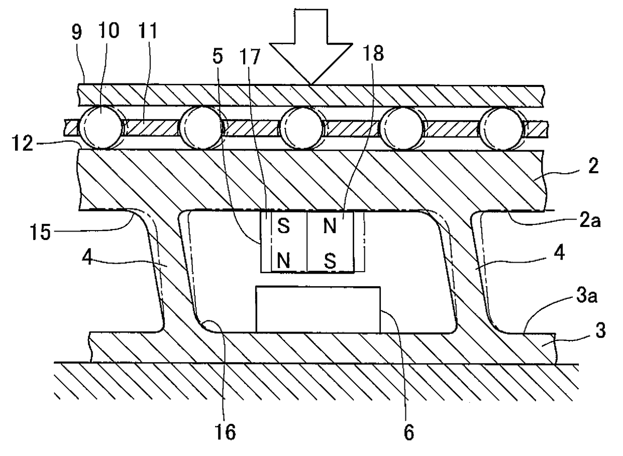
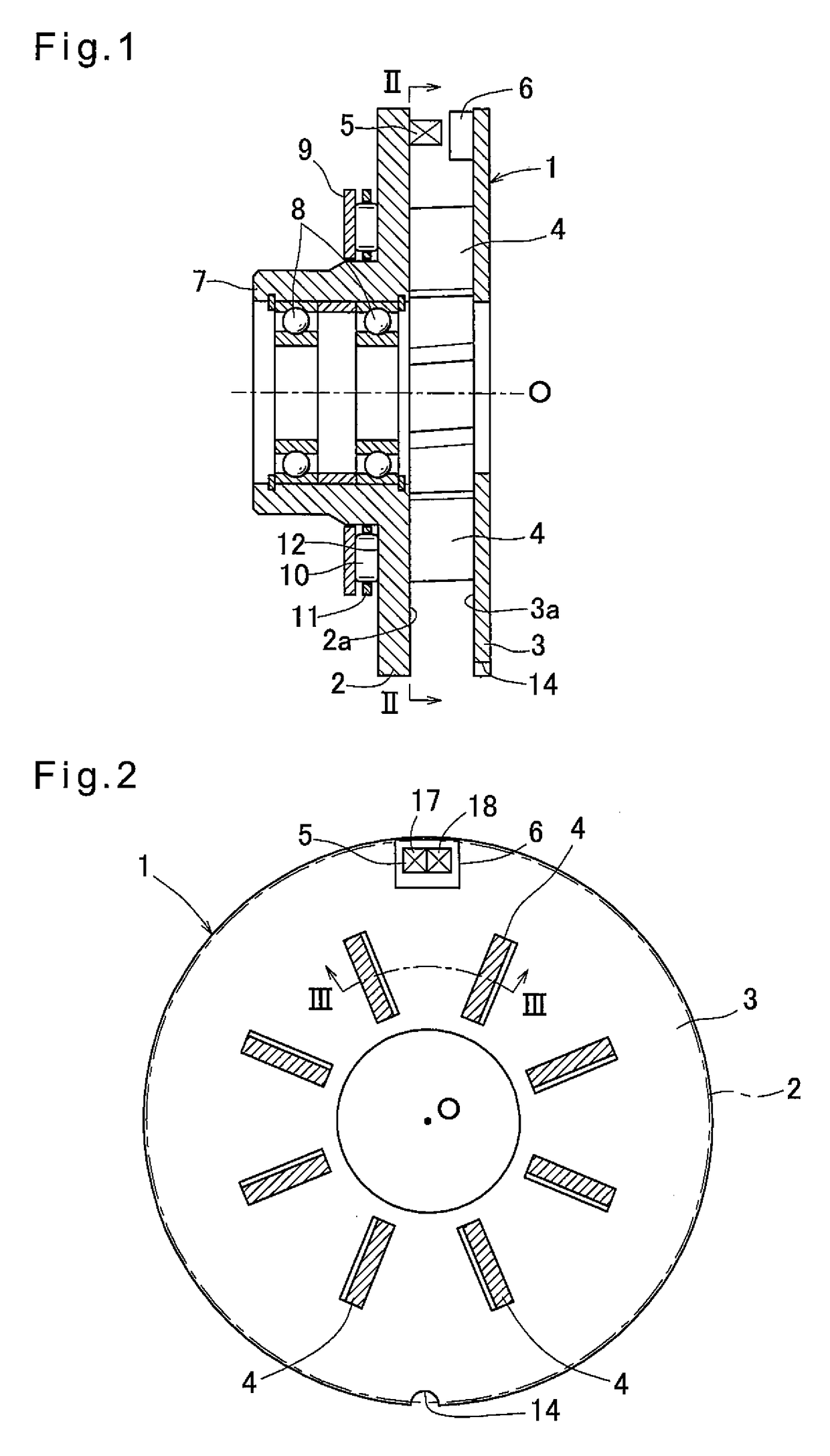
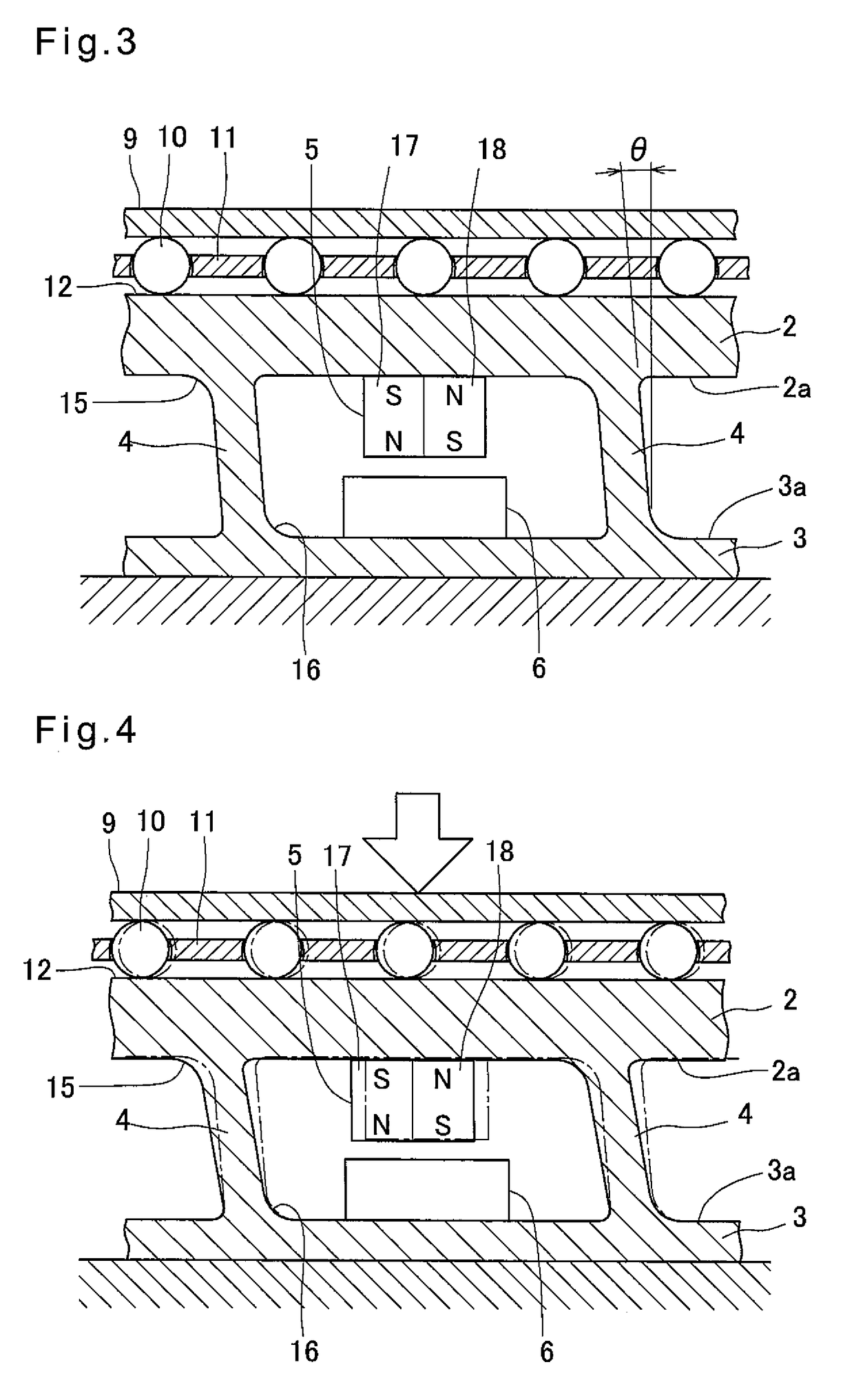
[0041]FIG. 1 shows a magnetic load sensor 1 embodying the present invention. This load sensor 1 includes a pair of parallel plates 2 and 3 extending parallel to, and axially spaced apart from, each other, and coupled together by a plurality of coupling pieces 4. The load sensor 1 further includes a magnetic target 5 mounted to the first parallel plate 2, and a magnetic sensor element 6 mounted to the second parallel plate 3.

[0042]The parallel plate 2 is an annular disk-shaped member having a circular outer periphery, as viewed from the axial direction. The parallel plate 2 may be made of metal such as iron. The parallel plate 2 is integrally formed with a cylindrical portion 7 extending from the radially inner edge of the parallel plate 2 in the direction away from the parallel plate 3. Radial bearings 8 are mounted in the cylindrical portion 7, and support a rotary shaft 30 (see FIG. 10).

[0043]The parallel plate 2 is axially supported by a thrust bearing 9. The thrust bearing 9 inc...


PUM

PropertyMeasurementUnit
inclination anglesaaaaaaaaaa

Abstract

A magnetic load sensor is provided which is high in axial rigidity. The load sensor includes a pair of parallel plate coupled together by coupling pieces. The coupling pieces are inclined relative to the axial direction such that when an axial load is applied to the parallel plates, the parallel plates are displaced relative to each other in a direction perpendicular to the axial direction, due to deflection of the coupling pieces. A magnetic target is mounted to the parallel plate, and a magnetic sensor element is mounted to the parallel plate such that when the parallel plates are displaced relative to each other in the direction perpendicular to the axial direction, the magnetic target and the magnetic sensor element are displaced relative to each other in the direction perpendicular to the axial direction.

Description

TECHNICAL FIELD[0001]This invention relates to a magnetic load sensor, and an electric brake system using this magnetic load sensor.BACKGROUND ART[0002]Typically, an electric brake system is configured to convert the rotation of an electric motor to an axial movement of a friction pad to press the friction pad against a brake disk, thereby generating a braking force. In order to control the braking force to a desired magnitude, many of such electric brake systems include a load sensor mounted at a portion which receives an axially rearward reaction force that acts on the friction pad when the friction pad is pressed against the brake disk.[0003]Such a load sensor mounted in an electric brake system is disclosed in JP Patent Publication 2004-301835A. The load sensor disclosed in that document includes a magnetic target which generates a magnetic field, a magnetic sensor element configured to detect the magnitude of the magnetic field generated by the magnetic target, and a spring con...

Claims


Application Information

Patent Timeline
Patent Type & Authority Patents(United States)
IPC IPC(8): G01L1/12F16D66/00F16D65/12F16D55/225G01L5/28G01L5/22
CPCG01L1/122F16D55/225F16D65/12F16D66/00G01L5/28F16D2066/005G01L5/225G01D5/12
Inventor MASUDA, YUI
Owner NTN CORP
Why Eureka
Try Eureka