
Reference voltage generator having noise cancelling function and CMOS image sensor using the same

a reference voltage and noise cancelling technology, applied in the field of reference voltage generators and cmos image sensors, can solve the problems of switching noise, noise increase horizontal noise in the cmos image sensor, and noise occurring due to a comparator supply voltage may be effectively cancelled in a common mode, so as to prevent switching noise

Active Publication Date: 2017-02-28
SK HYNIX INC
View PDF4 Cites 0 Cited by
  • Summary
  • Abstract
  • Description
  • Claims
  • Application Information

AI Technical Summary

Benefits of technology

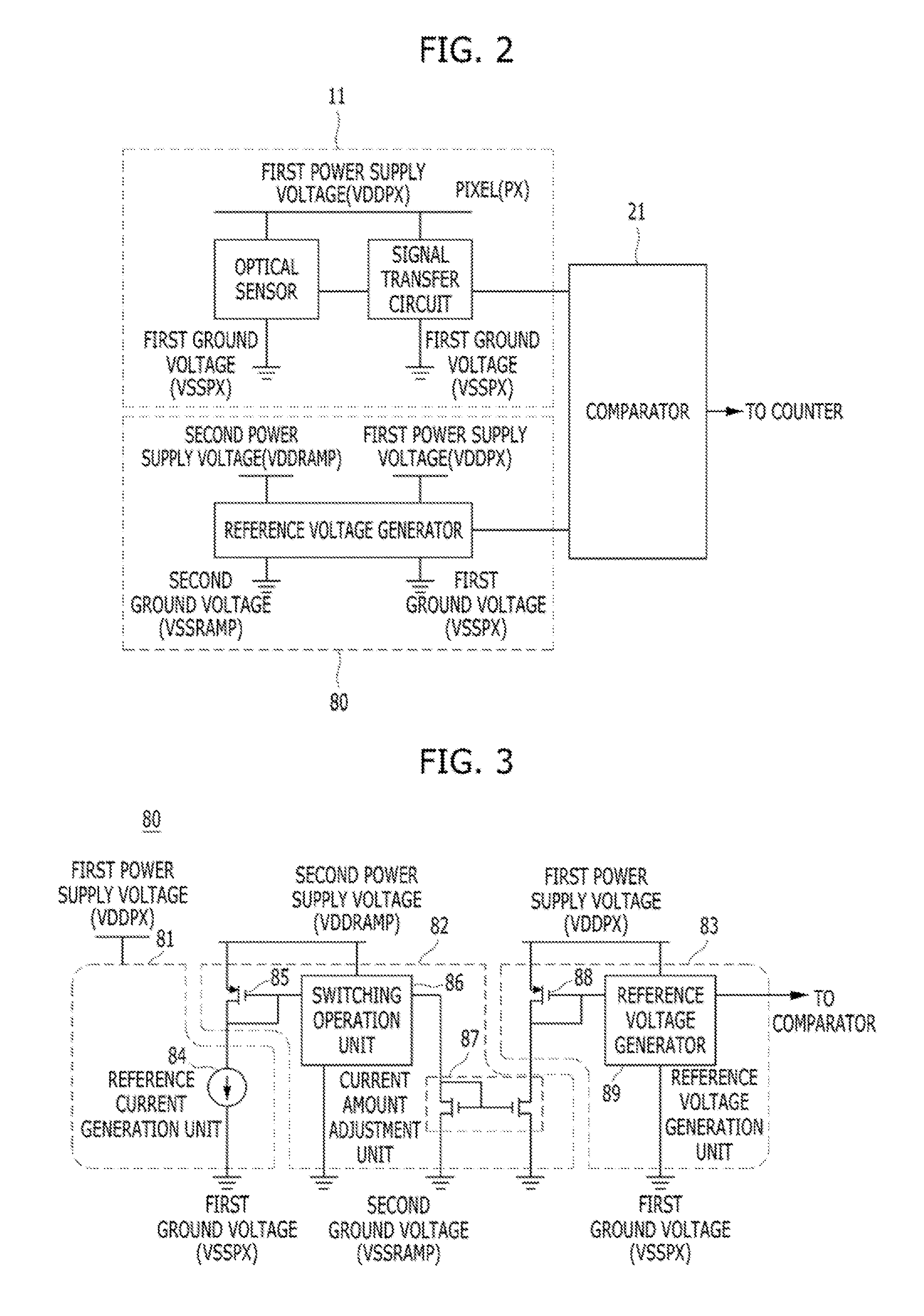
[0011]Various embodiments are directed to a reference voltage generator which uses a power supply designated for a reference signal in a switching operation-associated section, thereby preventing switching noise from being transferred to a readout circuit that is in the reference signal without being filtered.
[0012]Also, various embodiments are directed to a reference voltage generator capable of efficiently cancelling or suppressing power noise occurring due to the use of differential power supplies by using a diode-connected MOS and a current flowing therethrough.
[0013]Also, various embodiments are directed to a CMOS image sensor capable of efficiently cancelling or suppressing a power noise of a pixel signal by transferring the pixel signal and a reference signal to two input terminals of a comparator, based on the same power supply.

Problems solved by technology

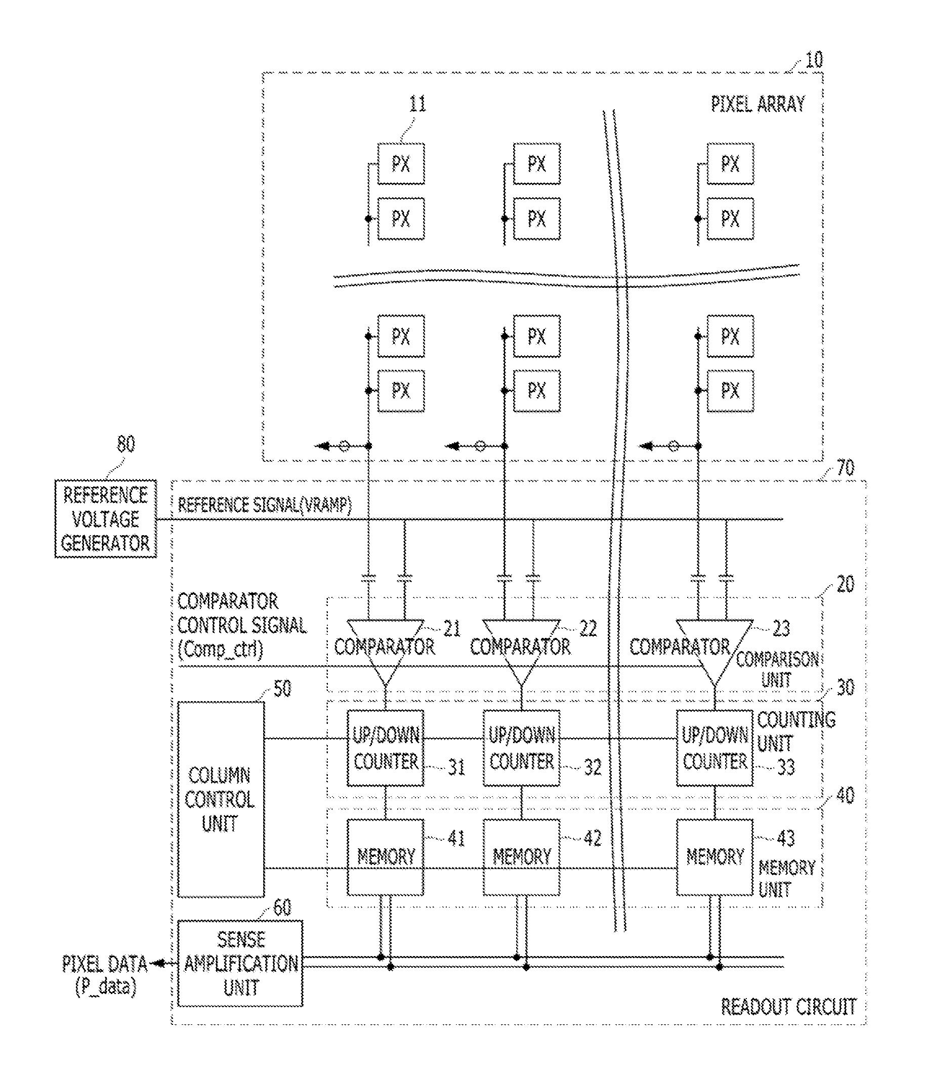
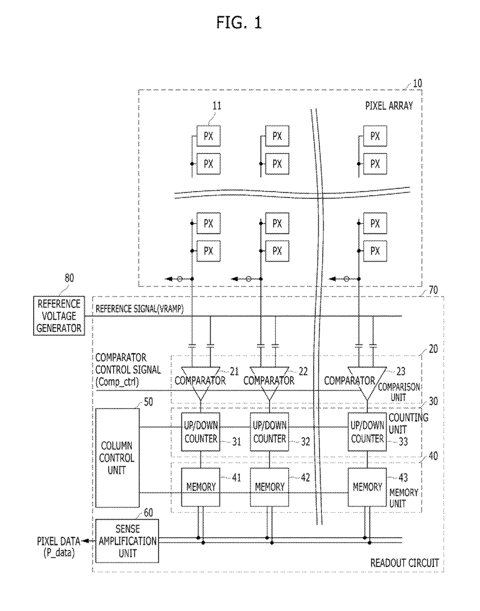
In a typical column parallel structure, each comparator of a readout circuit operates in a differential mode, and thus, noise occurring due to a comparator supply voltage may be effectively cancelled in a common mode.
However, since power noise occurring in a pixel is applied to a readout circuit and included in a pixel signal, the power noise is not cancelled-out in the readout circuit and is outputted in the pixel data.
At this time, the power may fluctuate due to a switching operation of a switching operation unit of the reference voltage generator, causing switching noise.
Such noise increases horizontal noise in the CMOS image sensor.

Method used


Image

  • Reference voltage generator having noise cancelling function and CMOS image sensor using the same
  • Reference voltage generator having noise cancelling function and CMOS image sensor using the same
  • Reference voltage generator having noise cancelling function and CMOS image sensor using the same

Examples


Embodiment Construction

[0022]Various embodiments will be described below in more detail with reference to the accompanying drawings. The present invention may, however, be embodied in different forms and should not be construed as limited to the embodiments set forth herein. Rather, these embodiments are provided so that this disclosure will be thorough and complete, and will fully convey the scope of the present invention to those skilled in the art. Throughout the disclosure, like reference numerals refer to like parts throughout the various figures and embodiments of the present invention.

[0023]When an element is referred to as being connected or coupled to another element, it should be understood that the former can be directly connected or coupled to the latter, or electrically connected or coupled to the latter via an intervening element therebetween. Furthermore, when it is described that one “comprises” (or “includes”) or “has” some elements, it should be understood that it may comprise (or includ...


PUM


Abstract

The reference voltage generator may include a reference current generation unit suitable for generating a reference current based on a first power supply voltage and a first ground voltage, a current amount adjustment unit suitable for adjusting a current amount of the reference current generated by the reference current generation unit based on a second power supply voltage and a second ground voltage, and a reference voltage generation unit suitable for generating a reference voltage corresponding to the reference current, of which the current amount is adjusted by the current amount adjustment unit, based on the first power supply voltage and the first ground voltage.

Description

CROSS-REFERENCE TO RELATED APPLICATIONS[0001]The present application claims priority of Korean Patent Application No. 10-2014-0145185, filed on Oct. 24, 2014, which is incorporated herein by reference in its entirety.BACKGROUND[0002]1. Field[0003]Embodiments of the present invention relate to a complementary metal-oxide semiconductor (CMOS) image sensor (CIS) and, more particularly, to a reference voltage generator and a CIS using the same, which are capable of preventing pixel signals from being distorted due to power noise (for example, ground noise and supply noise) by cancelling or suppressing the power noise in the readout path of the CIS.[0004]2. Description of the Related Art[0005]In a typical column parallel structure, each comparator of a readout circuit operates in a differential mode, and thus, noise occurring due to a comparator supply voltage may be effectively cancelled in a common mode.[0006]However, since power noise occurring in a pixel is applied to a readout circu...

Claims


Application Information

Patent Timeline
Patent Type & Authority Patents(United States)
IPC IPC(8): H04N5/335H03K17/16G05F1/46H04N5/374H04N5/378H04N5/357
CPCH03K17/165G05F1/468H04N5/357H04N5/374H04N5/378H04N25/617H04N25/76H04N25/75H04N25/60
Inventor AHN, PETER KYU
Owner SK HYNIX INC
Learn More