
Transfer switch for automatically switching between alternative energy source and utility grid

a technology of automatic switching and utility grid, applied in the field of transfer switches, can solve the problems of inconvenient operation of power network operation systems, inverter fault condition, shutting down, etc., and achieve the effect of reducing the energy level of the dc battery and reducing the dc voltage on the terminals of the battery

Active Publication Date: 2017-02-28
RELIANCE CONTROLS
View PDF46 Cites 3 Cited by
  • Summary
  • Abstract
  • Description
  • Claims
  • Application Information

AI Technical Summary

Benefits of technology

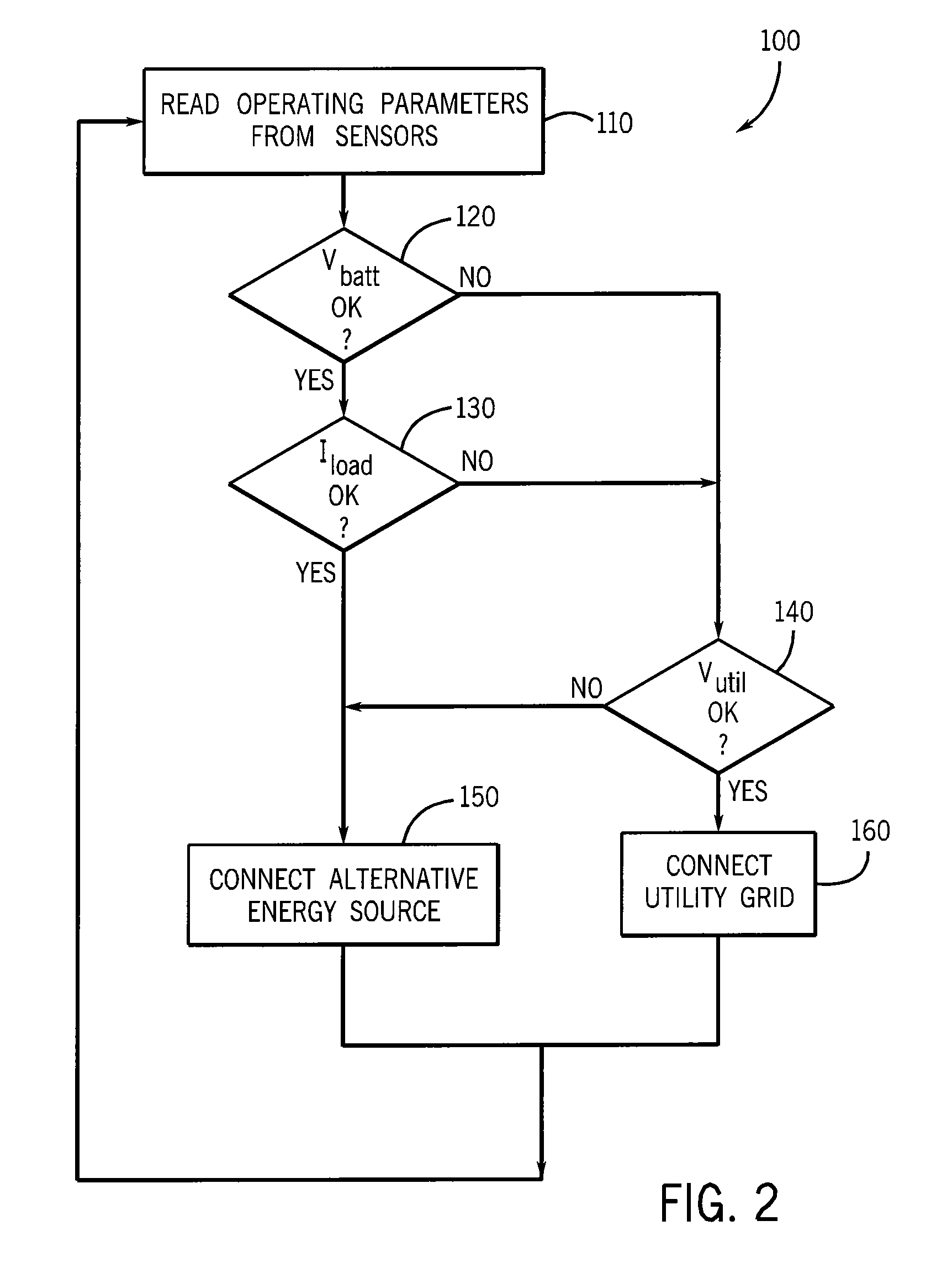
The patent describes a transfer switch that can switch between different power sources to ensure the system always has enough power to meet the needs of the loads. When the non-traditional power source cannot produce enough power, the transfer switch will switch to the battery to supplement the power. The amount of energy remaining in the battery indicates if the non-traditional power source can supply enough power. The transfer switch can switch power sources before the inverter reaches a fault condition and shuts down. This prevents any damage to the inverter or restricts the power available to the loads. The main technical effects of the patent text are to improve the reliability and stability of the power system, and prevent damage to the inverter during temporary loading conditions.

Problems solved by technology

However, a traditional automatic transfer switch is not well suited for an application in which the primary energy source is an alternative energy source and the secondary energy source is the utility grid.
If the alternative energy source is not producing sufficient power to supply the load and the battery has been drained, the inverter will experience a fault condition and shut down.

Method used


Image

  • Transfer switch for automatically switching between alternative energy source and utility grid
  • Transfer switch for automatically switching between alternative energy source and utility grid
  • Transfer switch for automatically switching between alternative energy source and utility grid

Examples


Embodiment Construction

[0021]The various features and advantageous details of the subject matter disclosed herein are explained more fully with reference to the non-limiting embodiments described in detail in the following description.

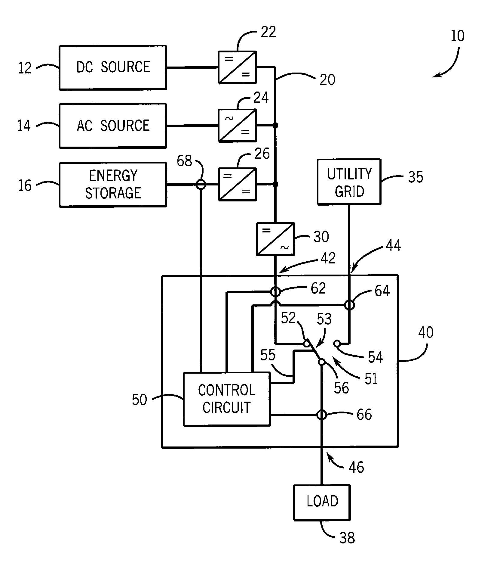
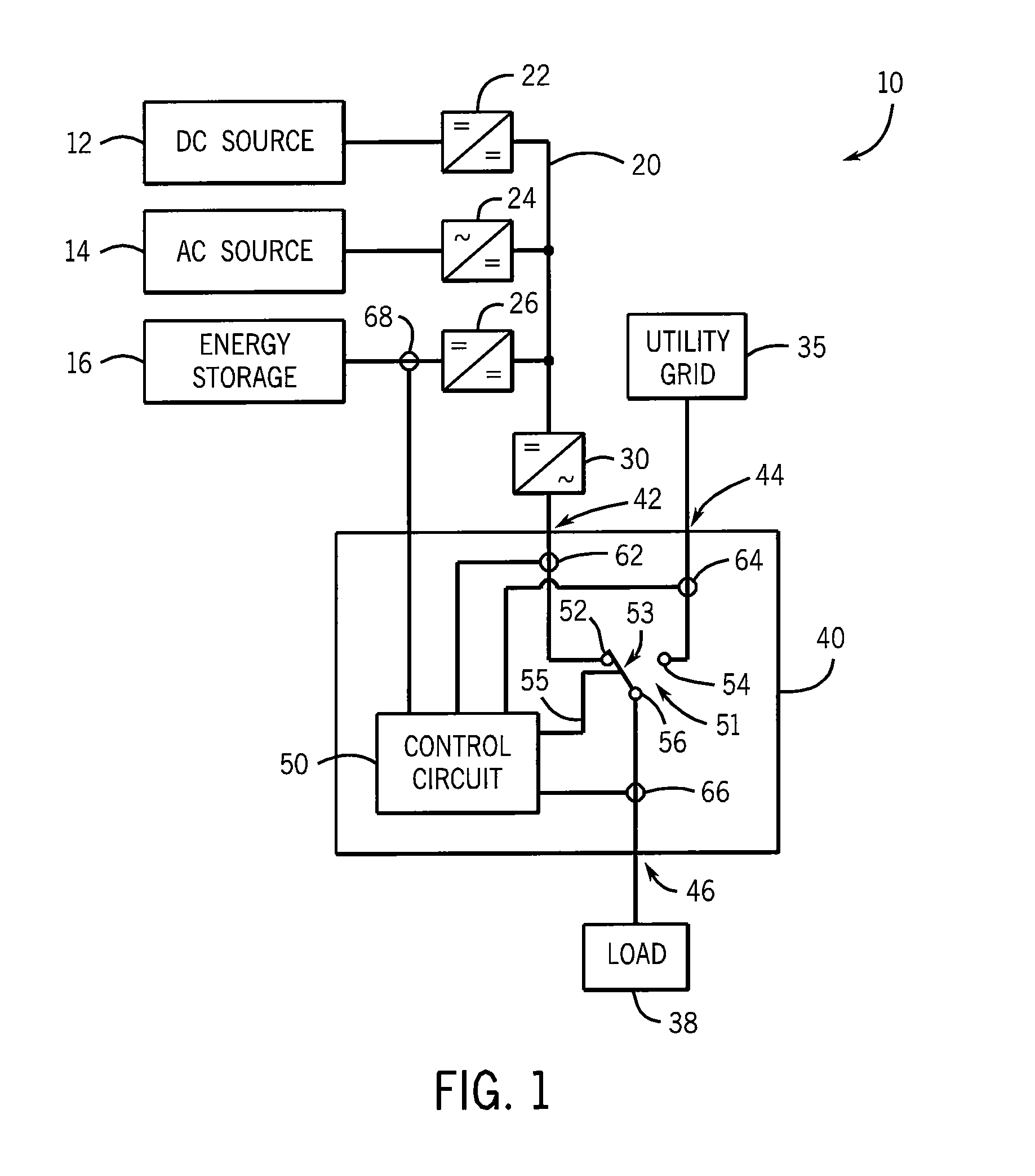
[0022]Referring to FIG. 1, a power generation system 10 may include multiple power sources. The power sources may be any suitable combination of power sources according to the requirements of a specific environment or application. A Direct Current (DC) power source 12, such as a photovoltaic array, generates power having a DC voltage. The DC voltage may be supplied directly to a DC bus 20, also referred to as a DC distribution system / network or a DC link, or the DC voltage may be supplied to the DC bus 20 via a DC-to-DC power converter 22. An Alternating Current (AC) power source 14, such as a wind turbine, water turbine, etc., generates power having an AC voltage. The AC voltage is supplied to the DC bus 20 via an AC-to-DC power converter 24. Because each of these alternati...


PUM


Abstract

An automatic transfer switch configured for connection to a non-traditional, full-time or intermittent power source, such as a wind turbine or solar panel, selectively connects the non-traditional power source as a primary power source and a utility-derived power source as a secondary power source. The intermittent power source includes an energy storage device, such as a bank of DC batteries, to supplement power delivery during periods of low energy production. The power is provided to an AC load via a DC-to-AC inverter. The transfer switch includes an input to monitor the voltage level on the energy storage device and will switch from the primary power source to the utility power source when the voltage level on the energy storage device drops below a preset level. Thus, a loading condition that exceeds the rating of the inverter will not fault the inverter or limit the power available to the loads.

Description

CROSS-REFERENCE TO RELATED APPLICATIONS[0001]This application claims priority to U.S. provisional application Ser. No. 61 / 477,399, filed Apr. 20, 2011, the entire contents of which is incorporated herein by reference.BACKGROUND OF THE INVENTION[0002]The subject matter disclosed herein relates to a transfer switch for automatically switching between a primary power source and a secondary power source. More specifically, a transfer switch for automatically switching between an alternative energy source and the utility grid is disclosed.[0003]Historically, it has been known to provide a transfer switch to automatically transfer a load from the utility grid to a backup generator in the event the utility grid was not operating properly. For example, the voltage present on the utility grid is monitored, and if the voltage drops below a preset value, the transfer switch switches to a backup power source, such as a generator. Further, the automatic transfer switch may provide a signal to th...

Claims


Application Information

Patent Timeline
Patent Type & Authority Patents(United States)
IPC IPC(8): H02J3/02H02J9/06
CPCH02J3/02H02J9/062Y02B10/72Y02E10/766Y10T307/615Y02B10/70Y02E10/76Y04S20/20Y02B70/30
Inventor CZARNECKI, NEIL A.
Owner RELIANCE CONTROLS
Learn More