Eureka AIR delivers breakthrough ideas for toughest innovation challenges, trusted by R&D personnel around the world.

Cutting assembly suitable for use on a drillable drill bit

a drilling bit and cutting assembly technology, applied in drilling pipes, drilling equipment, manufacturing tools, etc., can solve the problems of limiting the form of conventional drill bits, high cost of oil exploration in offshore regions, and long round trip time to pull out a drill bit and replace it with another one, so as to reduce the interference area

Active Publication Date: 2017-02-28
SCHLUMBERGER TECH CORP
View PDF9 Cites 0 Cited by
  • Summary
  • Abstract
  • Description
  • Claims
  • Application Information

AI Technical Summary

Benefits of technology

[0004]The cost of oil exploration particularly in offshore regions is extremely high. Thus it is in the interest of the operator to minimise the time taken to form a well bore. At great depths, the round trip time to pull out a drill bit and replace it with another one can be many hours. This “trip” time is seen as non-productive and wasteful, and a significant advantage can be gained, if, having drilled to target depth the drill bit does not have to be removed from the well bore. In this way, a trip could be saved.
[0044]Alternatively the step of providing the one or more detachment facilitating features may comprise providing one or more gaps between the cutter and the pre-formed pocket arranged so as to reduce the area of interference between the cutter and the pre-formed pocket.

Problems solved by technology

The cost of oil exploration particularly in offshore regions is extremely high.
At great depths, the round trip time to pull out a drill bit and replace it with another one can be many hours.
A limiting factor in many of the traditional techniques known in the art is the form of the conventional drill bits.
However, modern drill bits optimised for rock removal are generally unable to drill through the materials from which they themselves are constructed without sustaining a level of damage which would render the task of drilling the next section of rock formation impossible.
It is possible to drill through these traditional drill bits with a special tool known as a mill, but these tools are unable to effectively penetrate the subsequent rock formations and so the mill has to be removed from the well bore and replaced with an appropriate drill bit.
In these circumstances, the trip saving advantage gained by drilling with the casing string would be lost.
The casing drilling shoe described in PCT application number PCT / GB99 / 01816 is extremely expensive to produce due to the requirement to incorporate a displaceable outer drilling section.
In practice, these tools are also found to be sensitive to vibration and so they are not particularly robust which can cause mechanical failure during the drilling process.
A further drawback of the described tool is the use of aluminium for the inner section.
These strands then wrap themselves around the secondary drill bit so reducing the efficiency of any subsequent drilling process.
Furthermore, aluminium is easily eroded by the action of the drilling fluids which are necessarily used to clean the well bore.
In practice, and as recognised within the application itself, direct application of the relatively hard coatings to the crown and cutting member materials is difficult and in some combinations are just not practical.
For example, extremely hard tungsten carbide particles cannot easily be applied to crown sections when these are made from aluminium.
It is also recognised within the application that the described drill bit is not readily suitable for drilling through hard formations.
When deployed with hard formations the fragments of the relatively hard material tend to be sheared away from the crown section, thus quickly reducing the efficiency of the drilling process.
However, as is recognised in the art, lower blade heights generally result in lower drilling rates.
Such modifications to the casing bit however can be detrimental to the rate at which it can drill the subterranean formations and also the distance that the drill bit may drill before wearing out.
The requirement of a bespoke secondary drill bit to drill through the casing systems of PCT application number PCT / US2005 / 004106 also has obvious disadvantages since in the absence of such a bit the drilling operation is required to be suspended.
This can result in the mechanical failure of the standard drill bit leading to increased down time as the damaged drill bit and associated debris have to be removed from the well bore.
Furthermore, the design of the bespoke secondary drill bit may not be ideally suited to the particular formations that need to be drilled in the section below the casing drill bit.

Method used


Image

  • Cutting assembly suitable for use on a drillable drill bit
  • Cutting assembly suitable for use on a drillable drill bit
  • Cutting assembly suitable for use on a drillable drill bit

Examples


Embodiment Construction

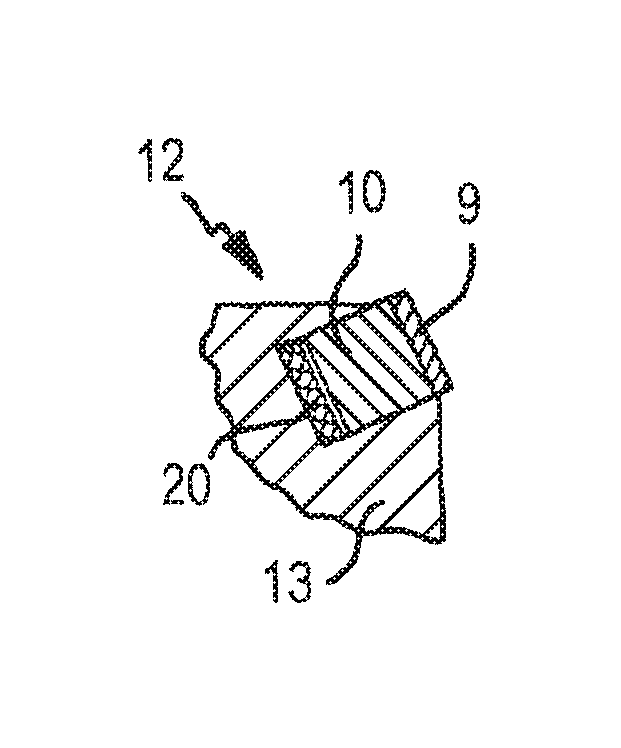
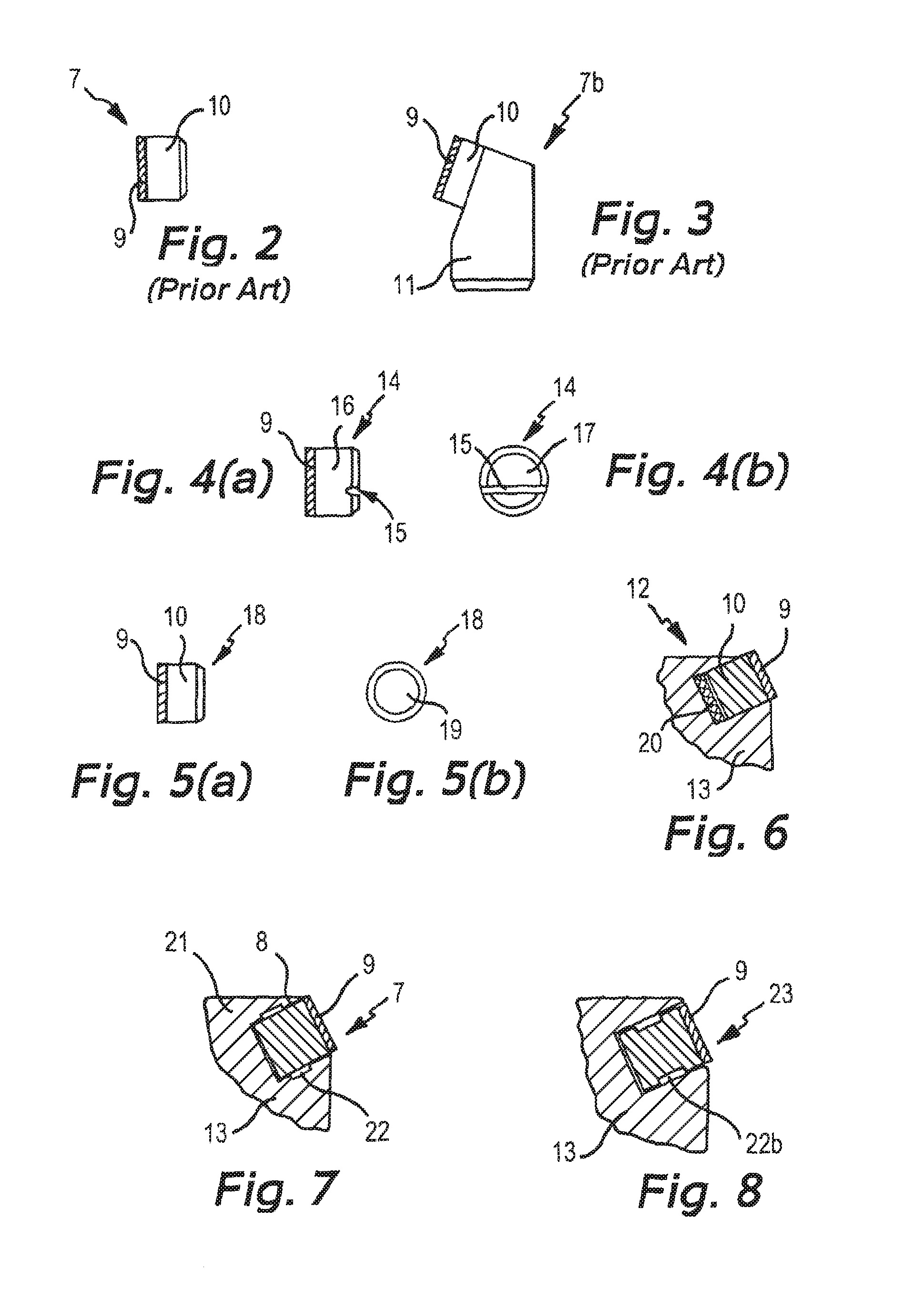
[0079]As discussed above, when developing a casing drill bit 1 it is important that the cutting assembly 12 i.e. the combination of the cutting members 5 and the attached cutters 7 is as robust as possible. This is to ensure that the cutting forces, and more importantly the impact forces experienced by the drill bit 1 do not cause the cutters 7 to chip or fracture or be sheared from the cutting members 5. For a drillable drill bit, represented generally in the following description by the reference numeral 13, these considerations are obviously still important. However, during a drill out operation the forces attempting to dislodge the cutters 7 from the body of the drill bit 13 have an opposite orientation to the normal drilling forces. This effect can be exploited by introducing a detachment facilitating feature at the interface between the cutters and the cutting members in order to provide a drillable drill bit 13 comprising cutters that can be retained upon a drillable drill bi...


PUM

PropertyMeasurementUnit
areaaaaaaaaaaa
diameteraaaaaaaaaa
depthaaaaaaaaaa

Abstract

A cutting assembly suitable for use on a drillable drill bit includes one or more cutting members comprising pre-formed pockets. A set of one or more cutters are located within the pre-formed pockets. A detachment facilitating feature is located at the interface between the cutting members and the cutters.

Description

[0001]The present invention relates to the field of hydrocarbon exploration. More specifically, the present invention concerns the provision of a cutting assembly suitable for use on a drillable drill bit.[0002]When drilling subterranean formations for the purpose of hydrocarbon exploration it is known in the art to initially drill a first section of a well bore having a first diameter and thereafter to remove the drill bit from the well bore. A first tubular member of lesser diameter, known as casing string, is then placed in the well bore and subsequently the annulus between the well bore and the outside of the casing string is filled with a cement. The purpose of the cement is to isolate certain of the subterranean strata from each other. The next stage of the operation involves passing a second drill bit, having a smaller diameter than the first, through the casing string so as to permit the drilling of a second section of the well bore beyond the previously attained depth of th...

Claims


Application Information

Patent Timeline
Patent Type & Authority Patents(United States)
IPC IPC(8): E21B10/573E21B10/43E21B17/14B23K1/20
CPCE21B10/573B23K1/20E21B10/43E21B17/14Y10T29/49826Y10T29/49885E21B10/633E21B7/20E21B10/42E21B10/567E21B10/62
Inventor WARDLEY, MICHAELBAVIDGE, MITCHELL
Owner SCHLUMBERGER TECH CORP
Why Eureka
Eureka Blog
Learn More