Eureka AIR delivers breakthrough ideas for toughest innovation challenges, trusted by R&D personnel around the world.

Magnetic interference detection system and method

a detection system and electromagnetic interference technology, applied in the field of electromagnetic interference detection system and method, can solve the problems of system potential inaccurateness, unreliable information being provided, and unreliable location data generated by the sensor

Active Publication Date: 2017-02-21
TYCO HEALTHCARE GRP LP
View PDF1026 Cites 17 Cited by
  • Summary
  • Abstract
  • Description
  • Claims
  • Application Information

AI Technical Summary

Benefits of technology

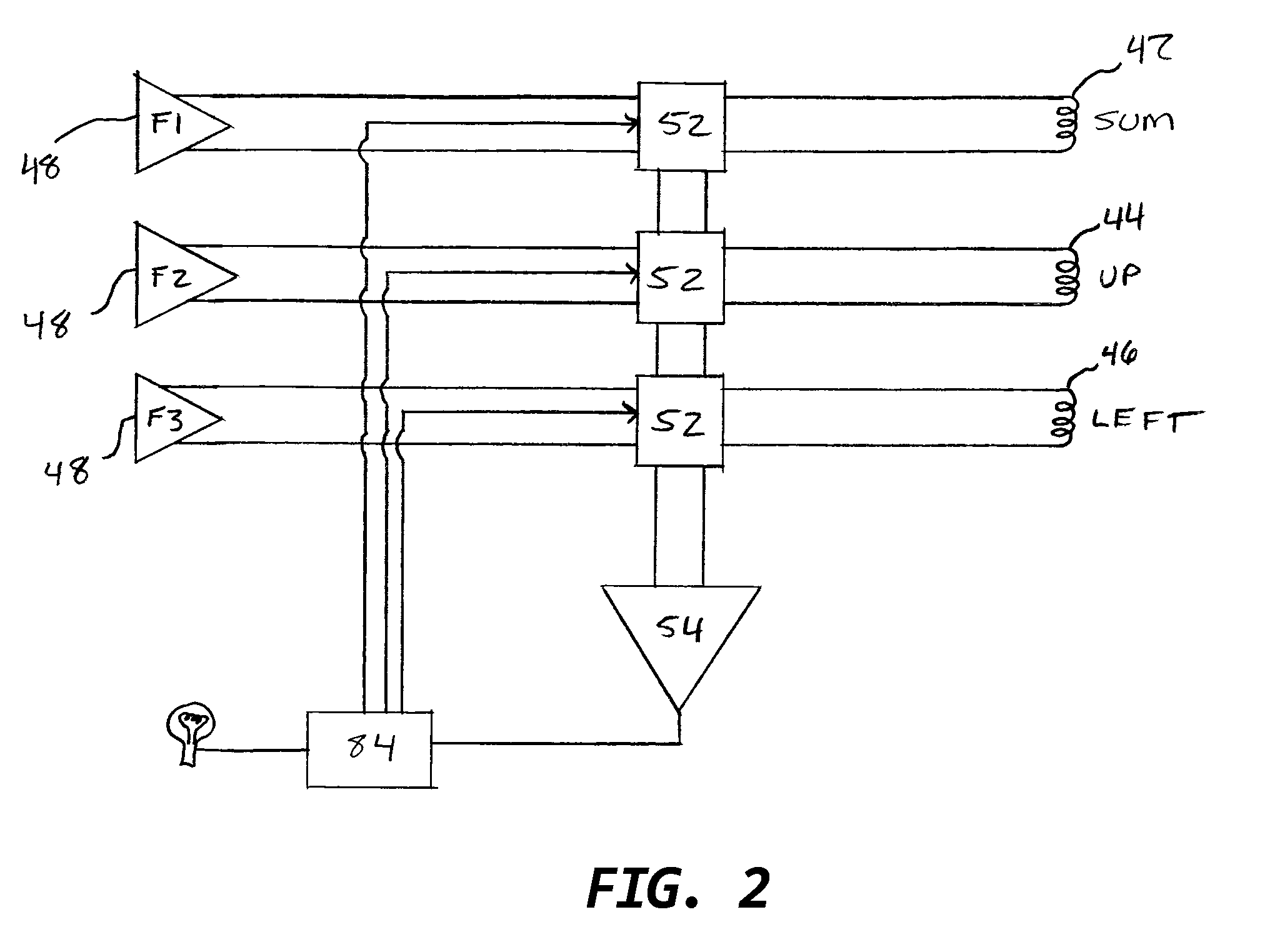
[0012]The three coils of the location board are each creating magnetic fields on independent frequencies (e.g. 2.5 kHz, 3.0 kHz, and 3.5 kHz). Utilizing three different frequencies allows the sensors to distinguish between the three different fields and process the data accordingly. Injecting a signal into the sensor coils on a fourth frequency (e.g. 4.0 kHz) would create a small magnetic field that would cause an induced voltage in the other coils having a corresponding frequency. The system could monitor this induced voltage for changes above a threshold level, indicated some sort of magnetic interference. The electronic system reading the sensor signals is designed to prevent the 4 Khz signals from interrupting the localization signals (2, 3 & 3.5 Khz) by means of analog filtering, digital filtering and, if needed, time domain differentiation (the 4 khz signals are generated at a low duty cycle at specific intervals when the localization signals are not measured).

Problems solved by technology

An alert is generated warning the user of the system that the magnetic field has been distorted and that the location data being generated by the sensor may be unreliable.
If a metal, or other ferrous object, is introduced into the sensing volume and somehow influences the magnetic field, the location system detects that the magnetic field has been altered or compromised and creates a warning condition that alerts the user that the information being provided may be unreliable.
Thus, if the inductance varies from the baseline above a threshold value, a warning will be displayed that the system is potentially inaccurate.

Method used


Image

  • Magnetic interference detection system and method
  • Magnetic interference detection system and method
  • Magnetic interference detection system and method

Examples


Embodiment Construction

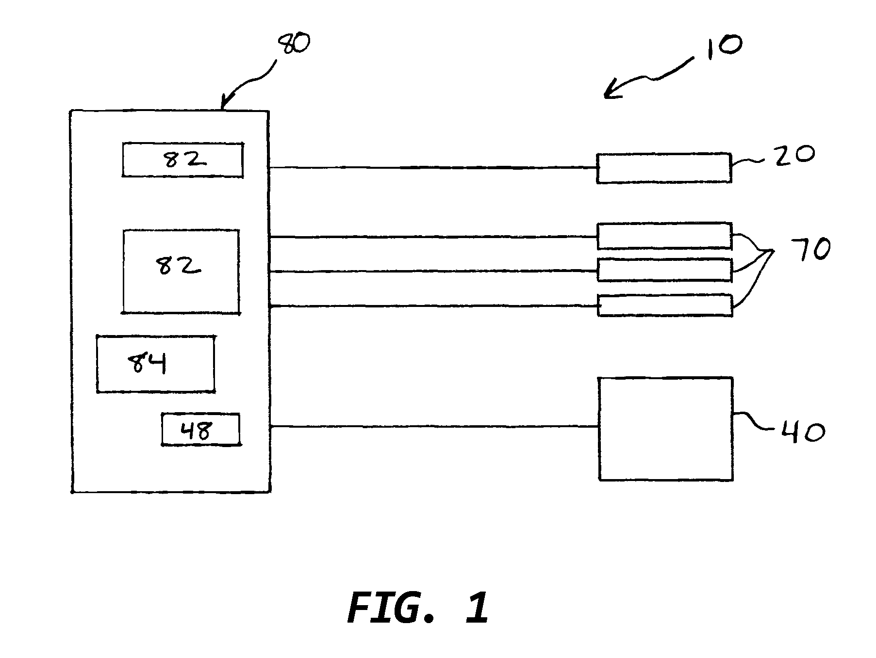
[0020]Referring now to the figures and first to FIG. 1, there is shown a location system 10 of the present invention. The location system 10 generally includes a locatable guide 20, a location board 40, a plurality of patient sensors 70, and a processing system 80.

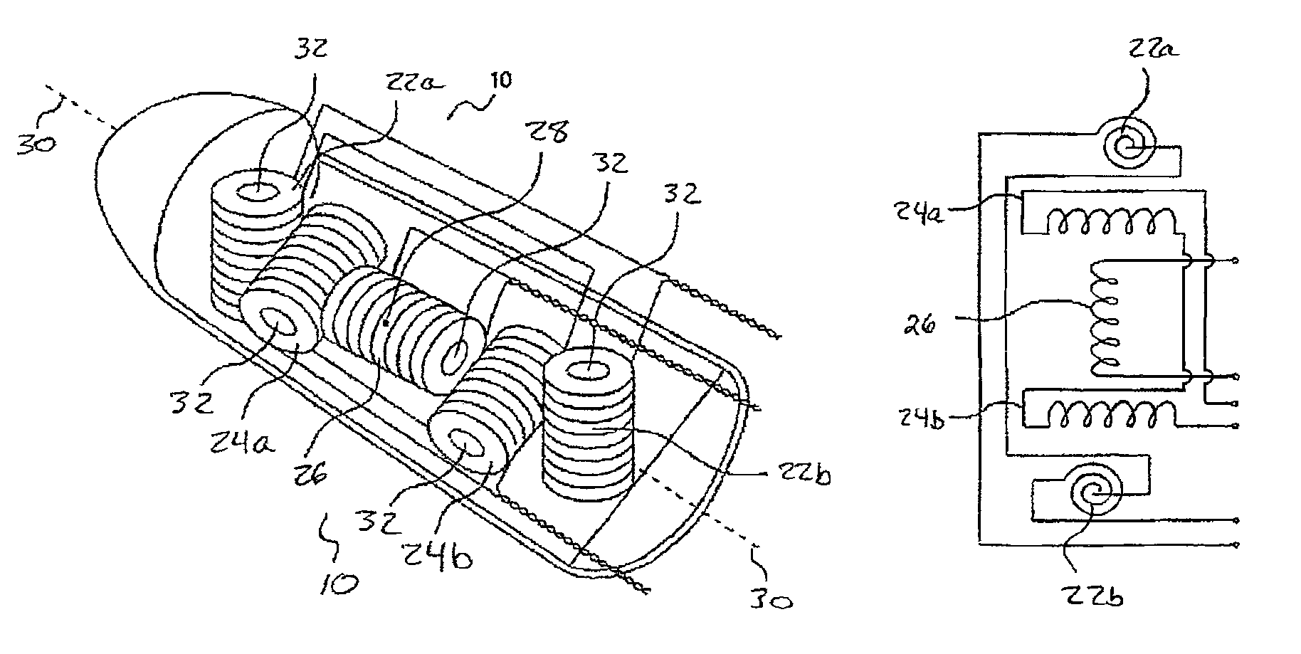
[0021]The locatable guide 20, as shown in FIGS. 4 and 5, is a probe having a receiver that generally includes a plurality of (preferably three) field component sensors 22, 24 and 26. Each of the field sensor components is arranged for sensing a different component of an electromagnetic field generated by the location board 40.

[0022]In one embodiment, shown in FIGS. 3 and 4, each field component sensor 22, 24 and 26 includes two sensor elements, 22a, 22b, 24a, 24b, 26a, and 26b, respectively. Typically, the sensor elements are coils of wire, and the sensed components are independent magnetic field components. The coils may be formed by wrapping wire around a core. The core may then be removed to form an air core at the cent...


PUM


Abstract

A system and method for tracking an object through a three dimensional space is provided that uses the generation and detection of various magnetic fields to provide three-dimensional location data. The integrity of the generated magnetic fields are monitored against a baseline in order to detect compromise by the unintentional introduction of a foreign metallic or magnetic object in the procedural space.

Description

RELATED APPLICATIONS[0001]The present application is related to and claims priority from provisional patent application Ser. No. 61 / 042,191, entitled “Magnetic Interference Detection System and Method” filed Apr. 3, 2008, the entirety of which is incorporated by reference herein; and is also related to and also claims priority from provisional patent application Ser. No. 61 / 042,578, entitled “Magnetic Interference Detection System and Method” filed Apr. 4, 2008, the entirety of which is incorporated by reference herein.BACKGROUND OF THE INVENTION[0002]Identifying and treating lung tissue abnormalities presents challenges that are somewhat unique to the lungs. If a tissue lesion or tumor is to be identified and excised surgically, the chest wall must be opened to provide access to the lungs. Opening the chest wall is a common procedure but one that presents risks of infection and lengthy recovery time, nonetheless.[0003]A desirable alternative to surgery, in terms of reducing patient...

Claims


Application Information

Patent Timeline
Patent Type & Authority Patents(United States)
IPC IPC(8): A61B5/05G01R33/04
CPCG01R33/04
Inventor ZUR, ODED
Owner TYCO HEALTHCARE GRP LP
Why Eureka
Eureka Blog
Learn More