
Force measurement assembly with damping and force measurement system including the same

a technology of force measurement and assembly, which is applied in the direction of force/torque/work measurement apparatus, instruments, gymnastics exercise, etc., can solve the problems of unnecessarily compromising the measurement accuracy of these highly sensitive measurement instruments, affecting the accuracy of the output generated by these measurement systems, and affecting the accuracy of the measurement. , to achieve the effect of increasing structural rigidity

Active Publication Date: 2017-02-14
BERTEC
View PDF36 Cites 47 Cited by
  • Summary
  • Abstract
  • Description
  • Claims
  • Application Information

AI Technical Summary

Benefits of technology

The patent text describes a new design for a base member that has increased structural rigidity. This is achieved by adding flanged portions to the base member or by using channel members with flanged portions. These features improve the overall strength of the base member, making it more durable and reliable.

Problems solved by technology

Due their high degree of measurement sensitivity, the accuracy of the output generated by these measurement systems is often adversely affected by vibrations imparted thereon by the building structure.
As such, the measurement accuracy of these highly sensitive measurement instruments is unnecessarily compromised by building vibrations.
Also, when force measurement systems are mounted on uneven surfaces or surfaces with undulations, the resulting instability of the measurement instrument often leads to measurement errors (i.e., resulting from the rocking of the measurement instrument).
In addition, when force measurement systems are affixedly attached to mounting surfaces that undergo deformation (e.g., a concrete slab of a building that flexes or deforms), the deformation of the mounting surfaces impart similar deformations on the components of the measurement instruments, thereby producing measurement errors.
In addition, the conventional rigid mounting arrangement of force measurement devices frequently results in a deleterious preloading on these devices.
This undesirable preloading may permanently deform various components of force measurement devices, which may also reduce the accuracy of the output generated by the force measurement systems.

Method used


Image

  • Force measurement assembly with damping and force measurement system including the same
  • Force measurement assembly with damping and force measurement system including the same
  • Force measurement assembly with damping and force measurement system including the same

Examples


first embodiment

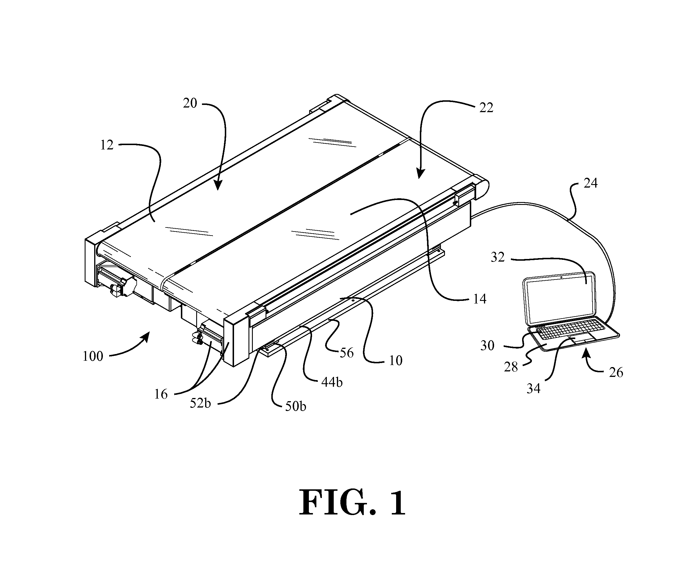
[0038]FIG. 1 is a top perspective view of a force measurement system with a force measurement assembly in the form of an instrumented treadmill, according to the invention, wherein the instrumented treadmill is provided with damping thereunder;

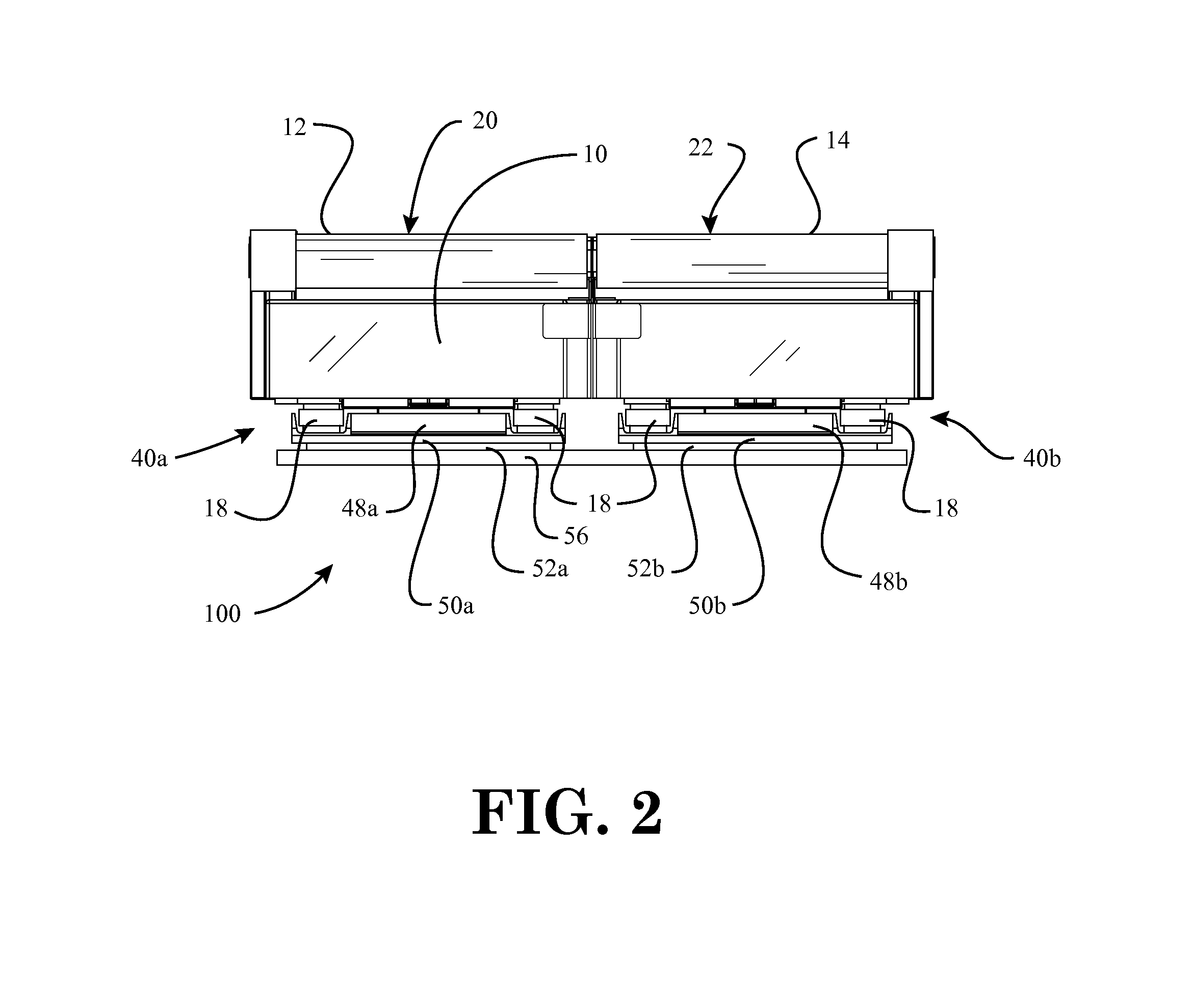
[0039]FIG. 2 is a rear end view of the instrumented treadmill with damping of FIG. 1;

[0040]FIG. 3 is a side view of the instrumented treadmill with damping of FIG. 1;

[0041]FIG. 4 is a bottom perspective view of the instrumented treadmill with damping of FIG. 1;

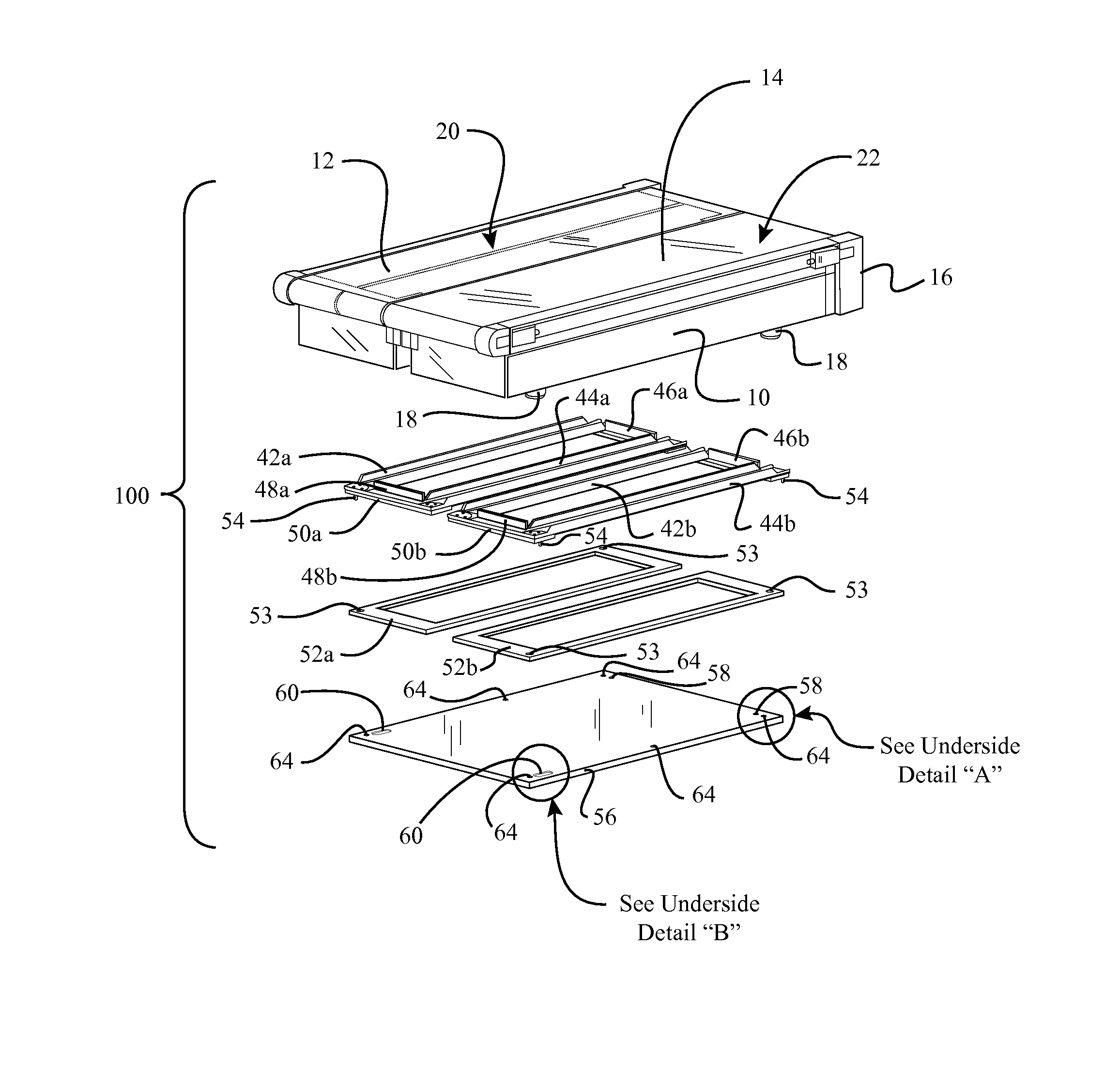
[0042]FIG. 5 is an exploded perspective view of the instrumented treadmill with damping of FIG. 1;

[0043]FIG. 6 is a top perspective view of the damping assemblies of the force measurement system of FIG. 1;

[0044]FIG. 7 is a bottom perspective view of the damping assemblies of the force measurement system of FIG. 1;

[0045]FIG. 8 is an enlarged detail view of the counterbore surrounding one of the circular apertures in the mounting plate of the instrumented treadmill assembly and the force p...

second embodiment

[0047]FIG. 10 is a top perspective view of a force measurement system with a force measurement assembly in the form of a force plate, according to the invention, wherein the force plate is provided with damping thereunder;

[0048]FIG. 11 is an exploded perspective view of the force plate with damping of FIG. 10; and

[0049]FIG. 12 is an enlarged detail view of an alignment pin at one corner of one of the damping assemblies of the force measurement system of FIG. 1 (Detail “C”).

[0050]Throughout the figures, the same parts are always denoted using the same reference characters so that, as a general rule, they will only be described once.


PUM

PropertyMeasurementUnit
forceaaaaaaaaaa
forcesaaaaaaaaaa
force measurementaaaaaaaaaa

Abstract

A force measurement assembly with damping is disclosed herein. The force measurement assembly includes a force measurement surface for receiving at least one portion of a body of a subject; at least one force transducer, the at least one force transducer configured to sense one or more measured quantities and output one or more signals that are representative of forces and / or moments being applied to the force measurement surface of the force measurement assembly by the subject; at least one base member disposed underneath the at least one force transducer or forming a part of the at least one force transducer; and a damping member disposed between the at least one base member and a mounting surface on which the force measurement assembly is disposed. A force measurement system that includes the force measurement assembly with damping is also disclosed herein.

Description

CROSS-REFERENCE TO RELATED APPLICATIONS[0001]Not ApplicableSTATEMENT REGARDING FEDERALLY SPONSORED RESEARCH OR DEVELOPMENT[0002]Not Applicable.NAMES OF THE PARTIES TO A JOINT RESEARCH AGREEMENT[0003]Not Applicable.INCORPORATION BY REFERENCE OF MATERIAL SUBMITTED ON A COMPACT DISK[0004]Not Applicable.BACKGROUND OF THE INVENTION[0005]1. Field of the Invention[0006]The invention generally relates to force measurement systems. More particularly, the invention relates to a force measurement assembly with damping and a force measurement system including the same.[0007]2. Background and Description of Related Art[0008]Force measurement systems are utilized in various fields to quantify the reaction forces and moments exchanged between a body and support surface. For example, in biomedical applications, force measurement systems are used for gait analysis, assessing balance and mobility, evaluating sports performance, and assessing ergonomics. In order to quantify the forces and moments res...

Claims


Application Information

Patent Timeline
Patent Type & Authority Patents(United States)
IPC IPC(8): G01D7/00G01L5/16G01M1/12A61B5/103
CPCG01L5/16A61B5/1036A63B2220/51G01M1/122A61B2562/0252A61B2562/046A61B2562/18A63B22/0242A63B2024/0093A63B2225/50A63B22/0207A63B22/0292G01L5/0061G06F1/1626
Inventor BERME, NECIPHOFFMAN, BENJAMIN ROBERT
Owner BERTEC
Learn More