Method and implant for stabilizing two bone portions separated by a cut or fracture

a technology of two bone segments and implants, applied in the field of medical technology, can solve the problems of limited efficiency and need for further surgery

Active Publication Date: 2017-02-14
WOODWELDING
View PDF23 Cites 1 Cited by
  • Summary
  • Abstract
  • Description
  • Claims
  • Application Information

AI Technical Summary

Benefits of technology

[0017]The material having thermoplastic properties may further contain foreign phases or compounds serving further functions. In particular, the thermoplastic material may be strengthened by admixed fibers or whiskers (e.g. of calcium phosphate ceramics or glasses) and such represent a composite material. The material having thermoplastic properties may further contain components which expand or dissolve (create pores) in situ (e.g. polyesters, polysaccharides, hydrogels, sodium phosphates), compounds which render the implant opaque and therewith visible for X-ray, or compounds to be released in situ and having a therapeutic effect, e.g. promotion of healing and regeneration (e.g. growth factors, antibiotics, inflammation inhibitors or buffers such as sodium phosphate or calcium carbonate against adverse effects of acidic decomposition). If the thermoplastic material is resorbable, release of such compounds is delayed.
[0023]As it is easily possible to make the whole implant from a bio-resorbable or bio-degradable material, the implant may be gradually replaced by new bone tissue bridging the cut or fracture at the place of the implant and therefore the implant does not need to be removed in a second surgical operation. Alternatively the implant may at least partly be made of a non-resorbable or non-degradable material and remain in the bone for permanently fixating the bone portions. This may be particularly advantageous in case of a bone whose healing capacity is impaired by disease (e.g. osteoporosis) or old age.
[0024]There is no necessity for the implant according to the invention to comprise any bone or bone replacement material; however, it may of course do so. Bone growth enhancing material such as e.g. allograft or autograft bone material, bone replacement material, sponges, BMP carriers, if used, are preferably arranged in the above named osteoconduction region of the implant, i.e. between the distal ends of the anchoring pins, wherein the named materials may be positioned between the bone tissue of the two bone portions to be stabilized before positioning and anchoring the implant or wherein the named materials may be preassembled with the implant. For such preassembly, implant surfaces around the osteoconduction region may carry retention means such as e.g. grooves or dents for retaining the named material. For accommodation of such materials, it will be advantageous to make room for them between the two bone portions, i.e. to e.g. provide a groove between the bores of the opening in which the implant is to be anchored, the groove having a larger depth than the bridge portion. The bridge portion will serve in such a case for not only stabilizing the anchoring pins relative to each other but also as means for preventing the above named materials from exiting from between the bone portions.

Problems solved by technology

The named stabilization of cut or fractured bones with the aid of plates and bone screws is well established but it is of an only limited efficiency, mainly because the plates are preformed and therefore are to be available in a large number of different types for a large number of different applications and different patients.
Furthermore, metallic plates and screws need to be removed in most cases, which make further surgery necessary when the cut or fractured bone is healed.

Method used


Image

  • Method and implant for stabilizing two bone portions separated by a cut or fracture
  • Method and implant for stabilizing two bone portions separated by a cut or fracture
  • Method and implant for stabilizing two bone portions separated by a cut or fracture

Examples


Embodiment Construction

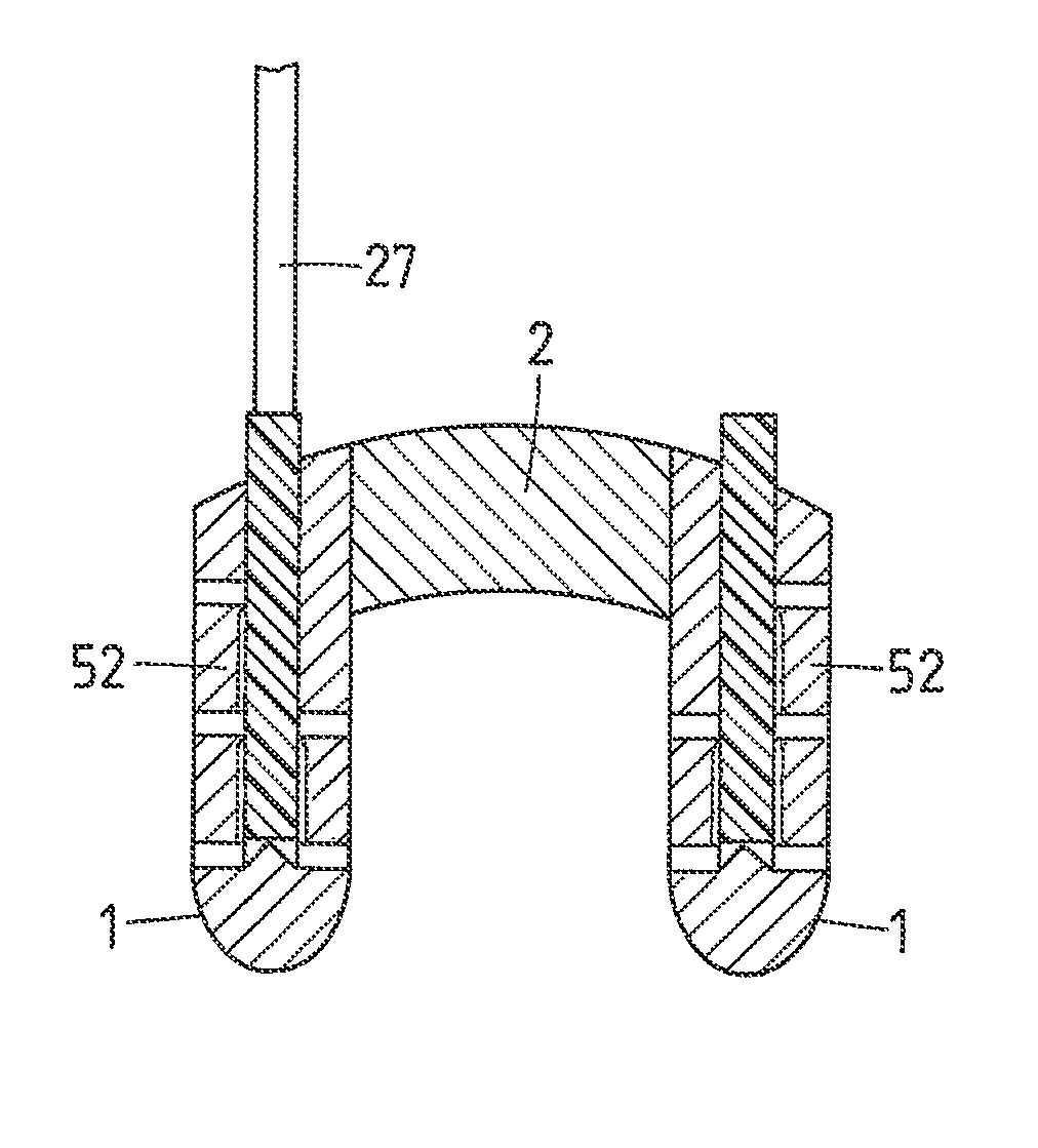
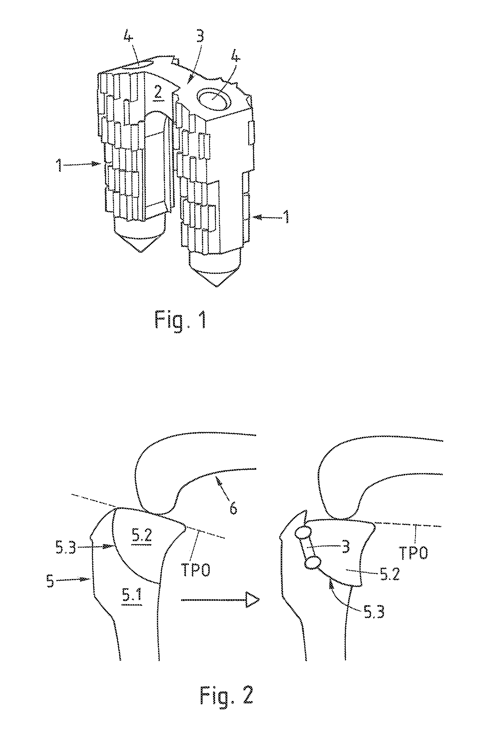
[0062]FIG. 1 is a three-dimensional illustration of a preferred embodiment of the implant according to the invention. The implant comprises two anchoring pins 1 and a bridge portion 2, arranged between the proximal ends of the anchoring pins 1. The whole implant is preferably made of a resorbable thermoplastic polymer (e.g. of polylactide, preferably LR706 by Böhringer). The anchoring pins 1 are slightly tapering and comprise a pointed distal end, the surface of the slightly tapering region being equipped with energy directors e.g. in the form of short axial ridges arranged in a plurality of adjacent rings, wherein the ridges of one ring are staggered in relation to the ridges of the adjoining ring or rings. Similar arrangements of energy directors are described in the publication US 2008 / 0109007 the disclosure of which is enclosed herein by reference.

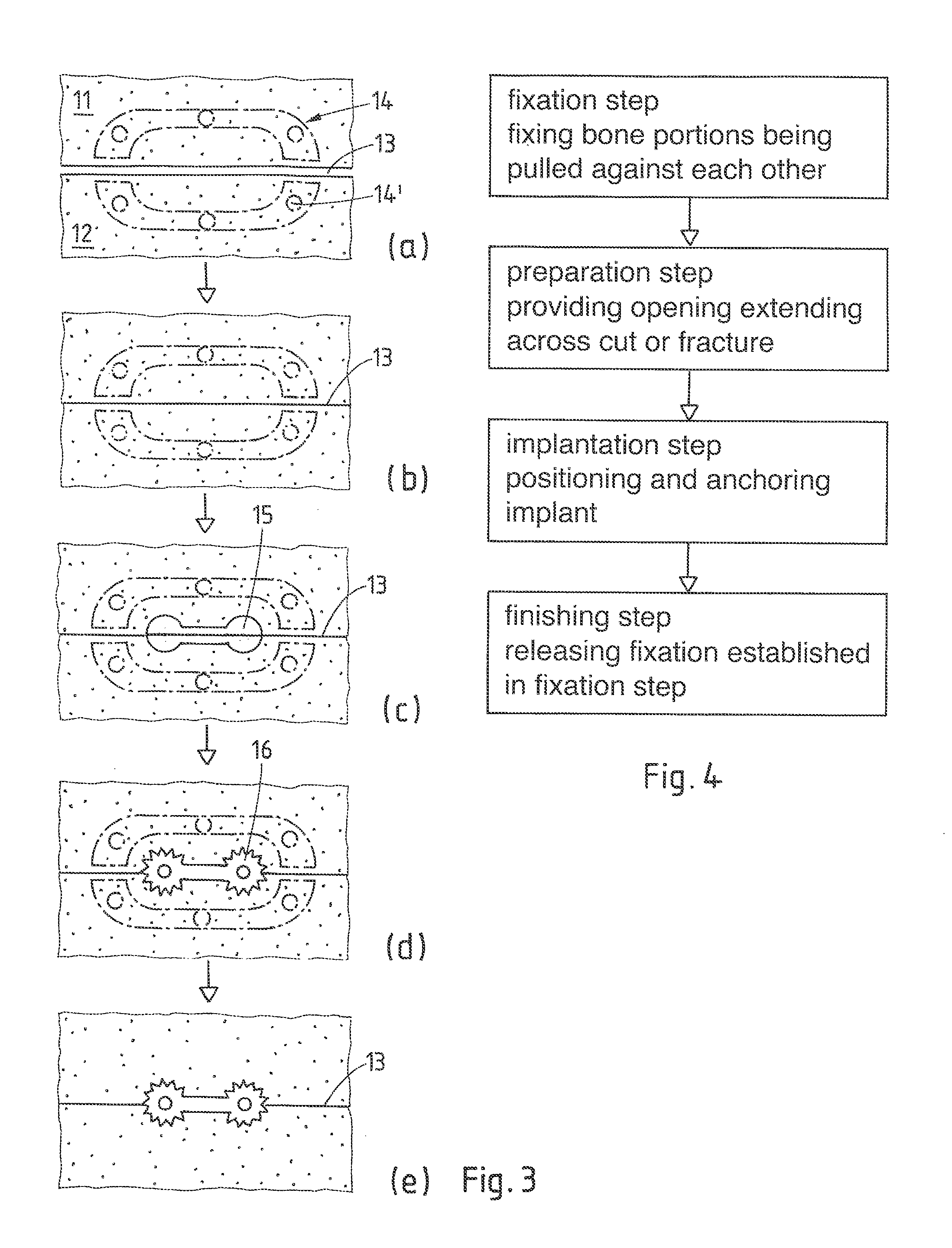
[0063]The opening provided for implantation of the implant according to FIG. 1, which opening reaches across the cut or fracture sepa...


PUM


Abstract

In a human or animal patient, two bone portions separated by a cut or fracture are stabilized in a desired position relative to each other by bringing the two bone portions into this desired position, by pulling them against each other, by providing an opening having a mouth on a bone surface and reaching across the cut or fracture and walls in both bone portions, by inserting an implant into the opening and anchoring the implant in the walls of the opening with the aid of a material having thermoplastic properties and energy transmitted into the implant for in situ liquefaction of at least part of the material having thermoplastic properties. One exemplary application of the stabilizing procedure concerns the two tibial bone portions separated by tibial plateau leveling osteotomy in a canine patient suffering from cranial cruciate ligament damage or rupture in a stifle joint.

Description

BACKGROUND OF THE INVENTION[0001]Field of the Invention[0002]The invention is in the field of medical technology and concerns a method and an implant for stabilizing two bone portions separated by a cut or fracture in a human or animal patient, in particular for stabilizing two bone portions being separated by osteotomy.[0003]Description of Related Art[0004]Osteotomy is a surgical procedure in which a bone is cut with the aim of being shortened, lengthened or re-aligned. Osteotomy is performed on human and animal patients mainly for realigning the load bearing surfaces in joints and for realigning bone portions in particular in the facio-maxillar region but also for re-aligning bone portions healed together with an undesired alignment relative to each other after a fracture. The bone portions separated by the osteotomy procedure mostly need to be re-aligned in a desired position relative to each other and to be stabilized in this position for being able to heal together again. Accor...

Claims


Application Information

Patent Timeline
Patent Type & Authority Patents(United States)
IPC IPC(8): A61B17/88A61B17/064A61B17/17A61B17/15A61B17/00
CPCA61B17/8866A61B17/0642A61B17/17A61B17/15A61B17/8872A61B2017/00831A61B2017/00955A61B2017/8655A61B17/68A61B17/90
Inventor MAYER, JORG
Owner WOODWELDING
Why Eureka
Try Eureka