
Display panel having touch function, display device, and control method for the same

a display panel and touch technology, applied in the field of touch display, can solve the problems of reducing the frame rate, increasing the time interval, and limiting so as to increase the report rate of the touch signal, reduce the loss of the touch panel, and increase the processing time of the touch signal of the display panel

Active Publication Date: 2017-02-07
TCL CHINA STAR OPTOELECTRONICS TECH CO LTD
View PDF3 Cites 0 Cited by
  • Summary
  • Abstract
  • Description
  • Claims
  • Application Information

AI Technical Summary

Benefits of technology

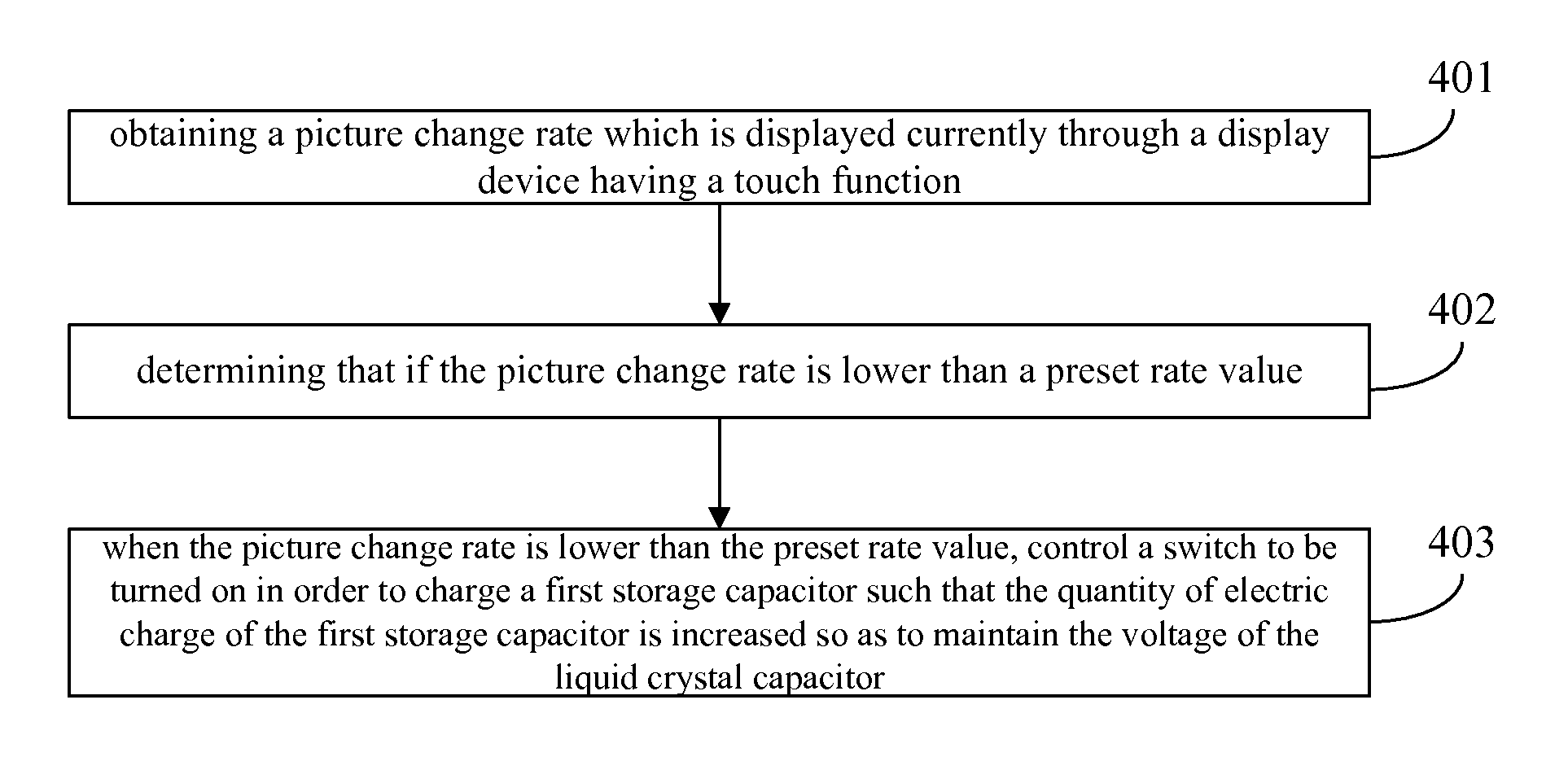
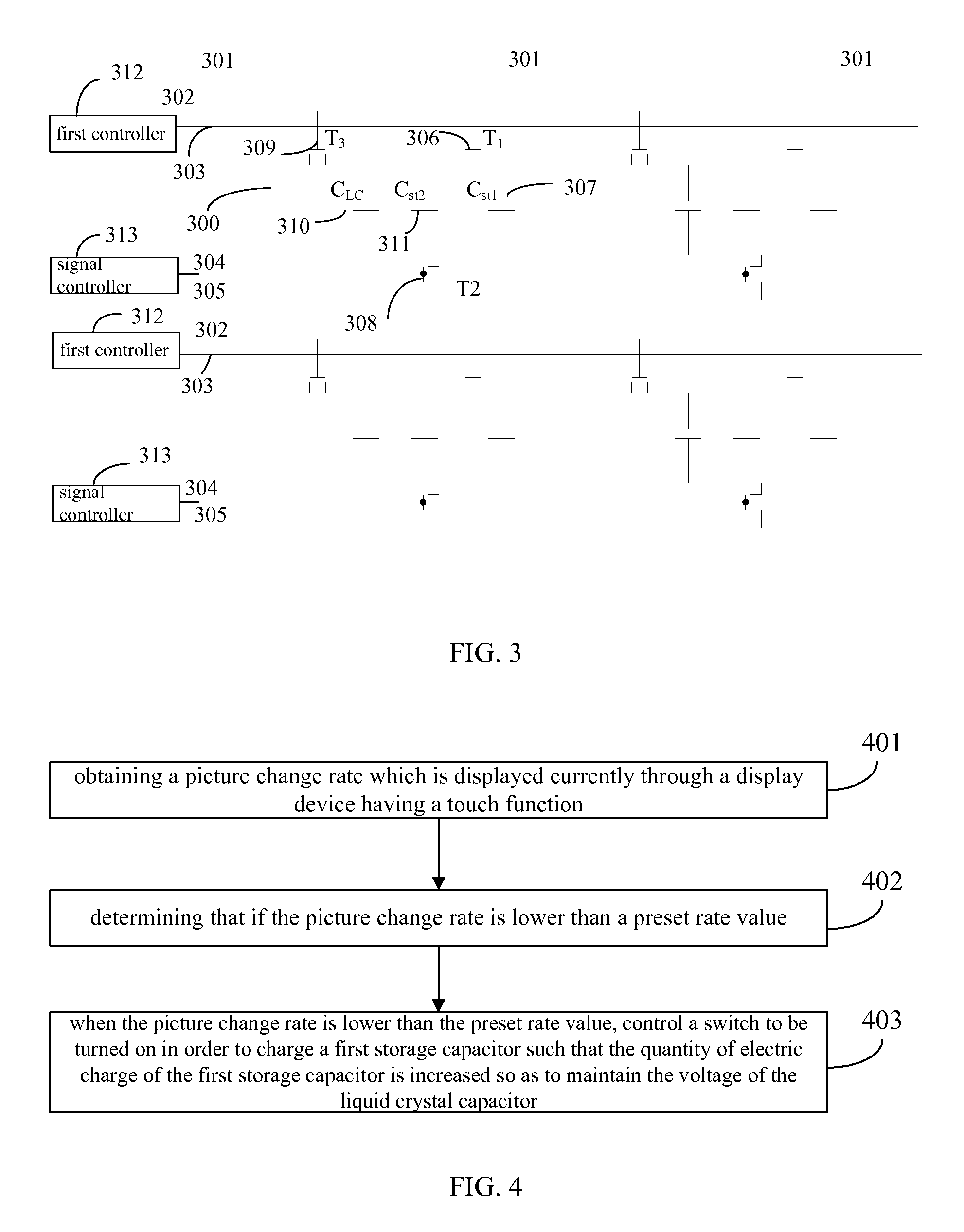
The present invention is related to a display panel with touch function, a display device, and control method for the same. The technology aims to increase the reporting rate of touch signals while displaying normal pictures. The invention adds a first switch and a first storage capacitor to compensate for leakage currents in the liquid crystal capacitor. This prevents lower frame rates and ensures display panels can still display normal pictures. Additionally, compensating the voltage at the common electrode helps maintain a consistent display. When the frequency of the display signal is decreased, the process time for touch signals is increased to increase reporting rate and decrease loss of touch panel.

Problems solved by technology

In the conventional art, the time-division multiplex control method will limit the time period for processing the touch signal such that the report rate of the touch signal is limited.
However, decreasing the frame rate means increasing the time interval.
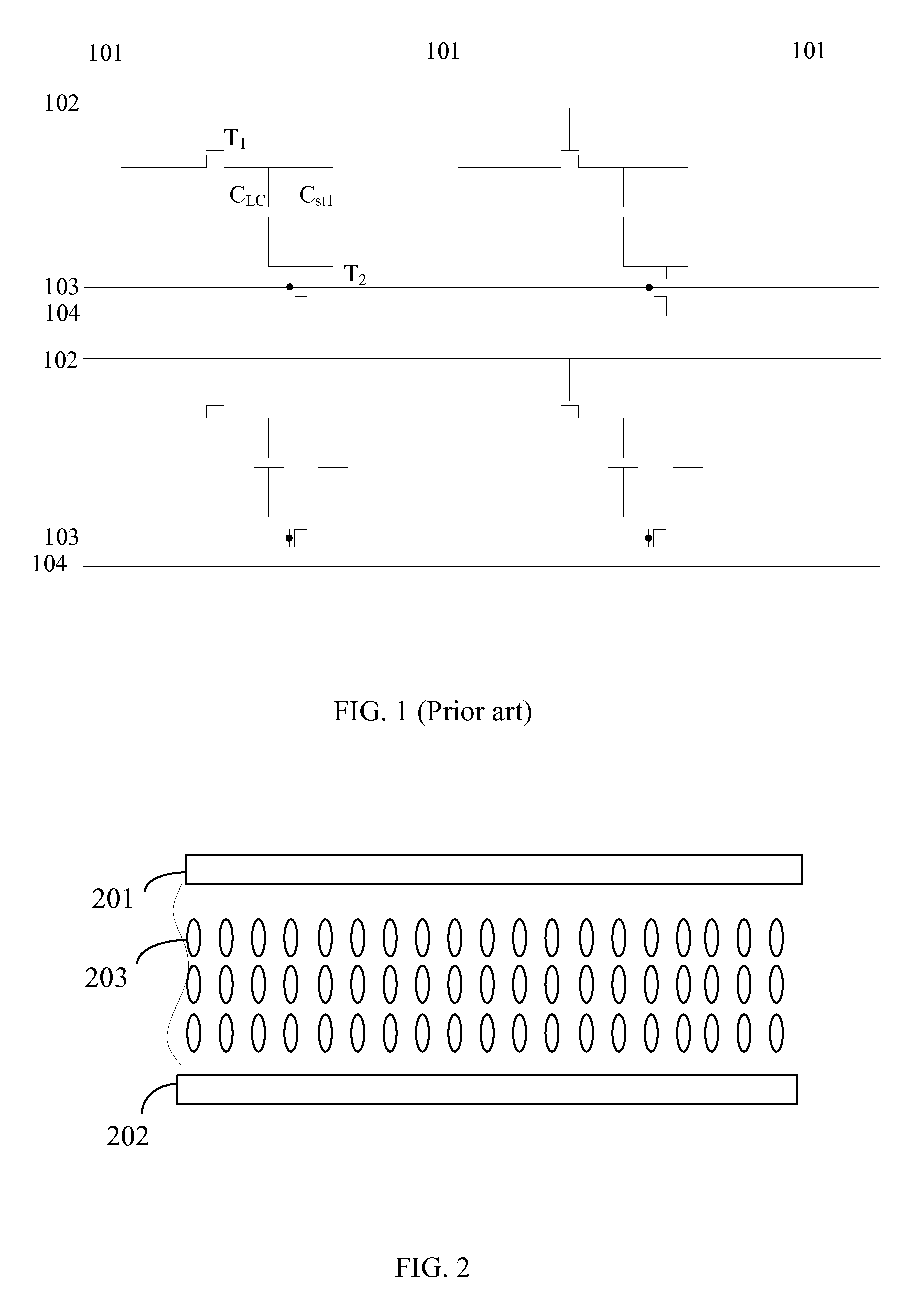
In the touch mode, although the switch T2 is turned off, a leakage current will still be generated in the circuit so as to decrease the voltage at two terminals of the liquid crystal capacitor and a normal voltage cannot be reached, which will seriously affect the display effect of the touch display panel.

Method used


Image

  • Display panel having touch function, display device, and control method for the same
  • Display panel having touch function, display device, and control method for the same
  • Display panel having touch function, display device, and control method for the same

Examples


Embodiment Construction

[0026]The following will combine drawings and embodiments for detailed description of the present invention.

[0027]With reference to FIG. 2, FIG. 2 is a schematic diagram of a display panel having a touch function according to an embodiment of the present invention. The display panel of the present embodiment includes a first substrate 201, a second substrate 202 disposed oppositely to the first substrate 201, and a liquid crystal layer 203 disposed between the first substrate 201 and the second substrate 202.

[0028]In order to realize a touch function and a display function, the display panel having a touch function generally requires touch electrodes and pixel electrodes. In the conventional art, the touch electrodes generally includes touch electrodes RX (not shown) disposed horizontally and touch electrodes TX disposed vertically. Wherein, the touch electrodes RX are located outside the second substrate 202. In order to reduce the thickness and weight of the display panel, in the ...


PUM

PropertyMeasurementUnit
voltageaaaaaaaaaa
electric chargeaaaaaaaaaa
capacitanceaaaaaaaaaa

Abstract

A display panel having a touch function, a display device, and a control method. The panel includes a first substrate having multiple pixel units. Each pixel unit includes a liquid crystal capacitor, a first switch, a second switch, and a first storage capacitor. A control, an input, and an output terminal of the first switch are respectively connected with a first controller, the liquid crystal capacitor, and the first storage capacitor. A control, an input, and an output terminal of the second switch are respectively connected with a signal controller, a common electrode, and the liquid crystal capacitor and the first storage capacitor. When a picture change rate is lower than a preset rate value, a turn-off time of the second switch is increased, and the first switch is turned on to increase the quantity of electric charge for maintaining a voltage of the liquid crystal capacitor.

Description

BACKGROUND OF THE INVENTION[0001]1. Field of the Invention[0002]The present invention relates to a touch display, and more particularly to a display panel having a touch function, a display device and a control method for the same.[0003]2. Description of Related Art[0004]A touch screen is also known as a touch panel. The touch screen is a liquid crystal display device which can receive an input signal of a touch event such as a finger contact. When a user touch a graphic button on the screen, a touch feedback system can determine a touch position according to a preset driving and scanning method such that the touched graphic button is determined and an instruction type is also determined. Comparing to the conventional mechanical button panel, the touch screen is more convenient, so that the touch screen has been widely used.[0005]A projected capacitive touch screen is one of common touch screens. The projected capacitive touch screen utilizes a touch technology of a capacitance chan...

Claims


Application Information

Patent Timeline
Patent Type & Authority Patents(United States)
IPC IPC(8): G06F3/041G02F1/1362G06F3/044G02F1/1333G09G3/36
CPCG06F3/0418G02F1/1362G02F1/13338G02F1/13624G02F1/136213G02F1/136286G06F3/044G06F3/0412G09G3/3659G06F2203/04111G09G2300/0842G02F1/1368G06F2203/04112G09G2320/10G06F3/04166G06F3/0445G06F3/0416
Inventor LU, YUCHENG
Owner TCL CHINA STAR OPTOELECTRONICS TECH CO LTD
Learn More