
Scanning driving circuit and touch liquid crystal display device

A scan drive circuit and scan drive technology, applied in static indicators, electrical digital data processing, optics, etc., can solve the problems of low sensitivity of touch operation and low report rate, so as to improve sensitivity and solve the problem of low report rate. Low, to solve the effect of low sensitivity of touch operation

Inactive Publication Date: 2015-10-07
TCL CHINA STAR OPTOELECTRONICS TECH CO LTD
View PDF7 Cites 5 Cited by
  • Summary
  • Abstract
  • Description
  • Claims
  • Application Information

AI Technical Summary

Problems solved by technology

[0007] The purpose of the present invention is to provide a scan driving circuit and a touch liquid crystal display device with a higher reporting rate and a higher touch operation sensitivity; to solve the reporting rate of the existing scanning driving circuit and touch liquid crystal display device Low technical issues with low sensitivity of touch operation

Method used


Image

  • Scanning driving circuit and touch liquid crystal display device
  • Scanning driving circuit and touch liquid crystal display device
  • Scanning driving circuit and touch liquid crystal display device

Examples


Embodiment Construction

[0035] The following descriptions of the various embodiments refer to the accompanying drawings to illustrate specific embodiments in which the present invention can be practiced. The directional terms mentioned in the present invention, such as "up", "down", "front", "back", "left", "right", "inside", "outside", "side", etc., are for reference only The orientation of the attached schema. Therefore, the directional terms used are used to illustrate and understand the present invention, but not to limit the present invention.

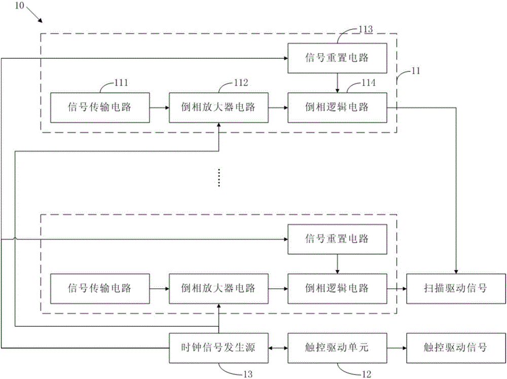
[0036] Please refer to figure 1 , figure 1 It is a structural schematic diagram of a preferred embodiment of the scanning driving circuit of the present invention. The scan driving circuit of this preferred embodiment can be used in a touch liquid crystal display panel. The scan driving circuit 10 includes a plurality of cascaded scan driving units 11 , a touch driving unit 12 and a clock signal generation source 13 . The scanning driving unit 11 is ...


PUM


Abstract

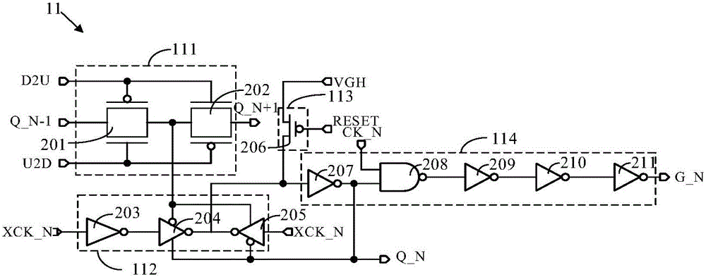
The invention discloses a scanning driving circuit which comprises a scanning driving unit, a touch driving unit and a clock signal generation source, wherein the scanning driving unit comprises a signal transmission circuit, an inverter amplifier circuit, a signal reset circuit and a phase-inversion logical circuit; when the touch driving unit outputs a touch driving signal, the scanning driving unit interrupts output of a scanning driving signal through a first clock signal and a second clock signal; and when the touch driving unit dose not output the touch driving signal, the scanning driving unit continuously outputs the scanning driving signal through the first clock signal and the second clock signal. The invention further provides a touch liquid crystal display device. According to the scanning driving circuit and the touch liquid crystal display device provided by the invention, through the interrupt processing of the first clock signal and the second clock signal, and the report rate of the liquid crystal display device is increased and sensitivity of touch operation is improved.

Description

【Technical field】 [0001] The present invention relates to the technical field of liquid crystal display, in particular to a scanning driving circuit and a touch liquid crystal display device. 【Background technique】 [0002] The touch panel (Touch Panel) has been widely used in smart phones, tablets / e-books, notebook computers, POS / KIOSK, game consoles, ATM machines and other fields. In the next few years, touch panels will grow rapidly, especially in fields such as mobile phones, tablet computers, portable multimedia players (PMP / MP3), and personal navigation devices. At the same time, touch panels are expected to achieve breakthroughs and growth in the application of large-size screens, such as All-In-One computers. [0003] Generally speaking, for touch technology, there are two forms of driving electrode (Tx) scanning. One is to perform driving scanning during the blanking time after the display screen is scanned. In this way, for a 60Hz touch liquid crystal display devi...

Claims


Application Information

Patent Timeline
Patent Type & Authority Applications(China)
IPC IPC(8): G09G3/36G02F1/1333
CPCG09G3/3677G09G2310/0286G09G2310/0291G09G2310/08G06F3/04184G02F1/13338G06F3/04166
Inventor 肖军城
Owner TCL CHINA STAR OPTOELECTRONICS TECH CO LTD
Learn More