
Inserting bypass structures at tap points to reduce latch dependency during scan testing

a bypass structure and latch technology, applied in the direction of electronic circuit testing, measurement devices, instruments, etc., can solve the problems of timing related errors in the test path, and achieve the effects of reducing fail data, improving diagnostic time, and improving production

Inactive Publication Date: 2017-01-17
INT BUSINESS MASCH CORP
View PDF13 Cites 0 Cited by
  • Summary
  • Abstract
  • Description
  • Claims
  • Application Information

AI Technical Summary

Benefits of technology

The system described in this patent aims to improve the testing of integrated circuits by identifying and reducing fail data. It also aims to improve production efficiency by injecting another scan path without affecting other parts of the scan chain. This system uses bypass structures, injection points, and partitioned scan chains to detect and analyze downstream components that might have been previously indeterminable. Overall, this system provides faster and more effective testing of integrated circuits.

Problems solved by technology

Faults resulting from manufacturing defects can cause timing related errors in the test path.

Method used


Image

  • Inserting bypass structures at tap points to reduce latch dependency during scan testing
  • Inserting bypass structures at tap points to reduce latch dependency during scan testing
  • Inserting bypass structures at tap points to reduce latch dependency during scan testing

Examples


Embodiment Construction

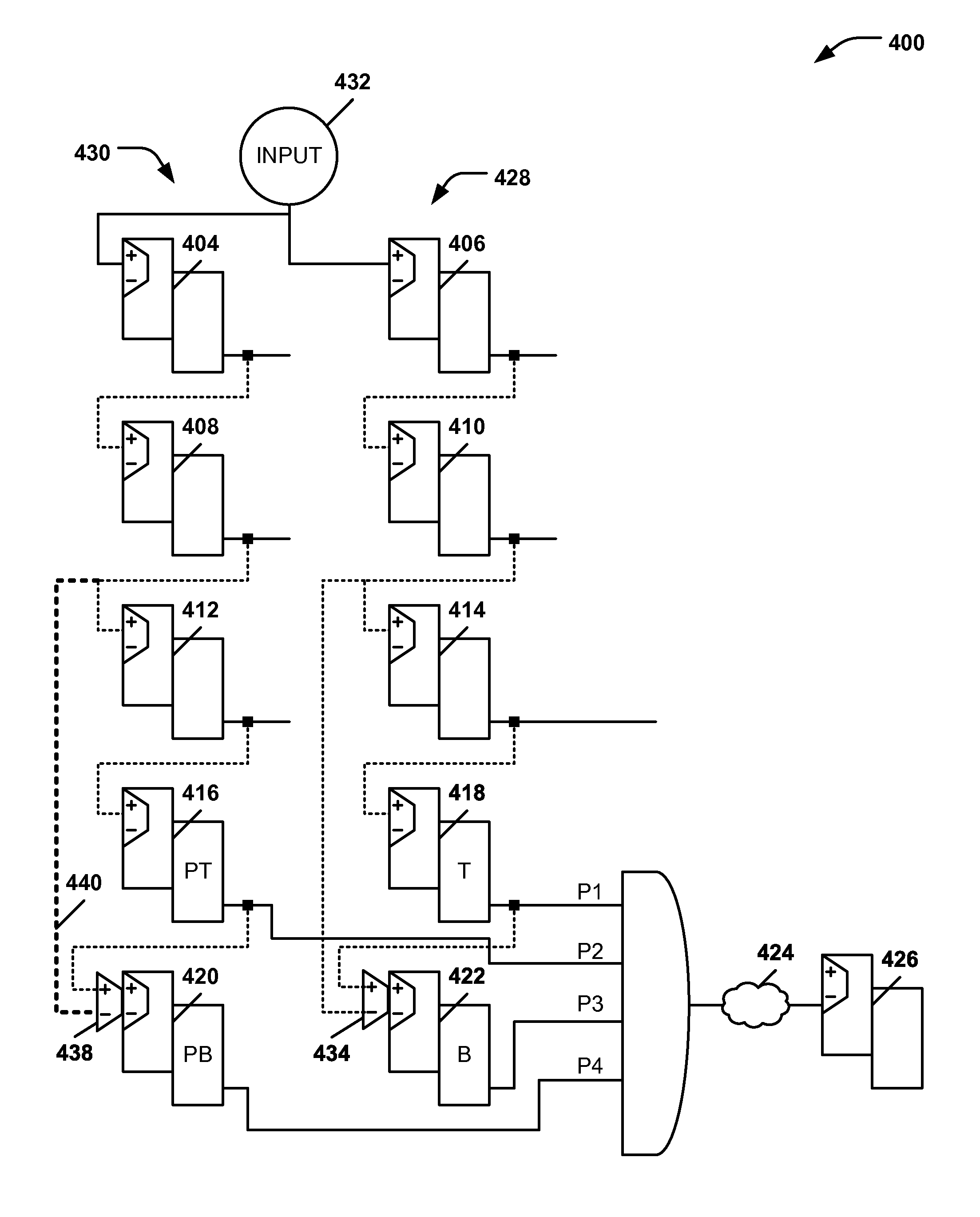
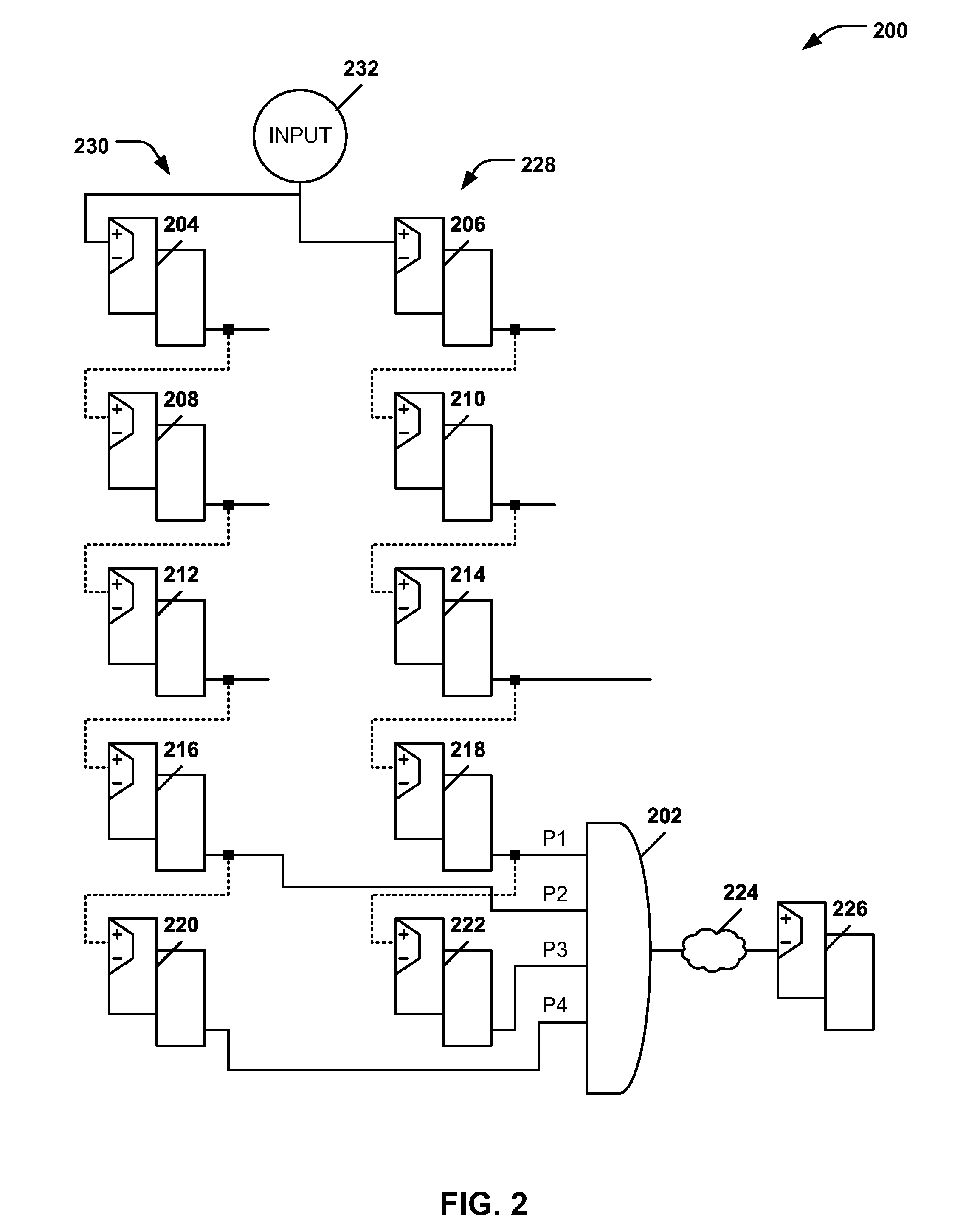
[0015]An embodiment of a system may automatically identify problem areas of a circuit and determine how and where to modify a scan path to remove dependencies. An embodiment of a system may logically analyze scan paths to identify circuit configurations where a dependency may cause a functional status of a component to be indeterminable (e.g., because it cannot be tested). The system may increase an amount of a combination logic path that may be tested and may facilitate transition fault testing improvements.

[0016]An embodiment of a system may insert a multiplexer into a scan chain at a tap point to enable circuit testing of components exhibiting latch dependency. A valid tap point may comprise a scan position that does not contribute to a same cone of logic. A cone of logic may include combination logic in a circuit that resolves to a single point.

[0017]Problematic configurations may include scan latch adjacency and parallel latches fed by a common scan input. Scan latch adjacency ...


PUM


Abstract

A method and apparatus are provided to test an integrated circuit by identifying first and second components of an integrated circuit. The first and second components may share a relationship that causes the first and second components to generate a matching binary output in response to an input to the integrated circuit. A tap point may be selected within the integrated circuit. The tap point may be located at a point in the integrated circuit where an insertion of a bypass structure would affect the relationship. The bypass structure may be inserted at the tap point, and the bypass structure may be used to conduct a test of the integrated circuit.

Description

I. CROSS REFERENCE TO RELATED APPLICATIONS[0001]This application is a continuation application and claims priority from U.S. patent application Ser. No. 14 / 568,312, entitled “INSERTING BYPASS STRUCTURES AT TAP POINTS TO REDUCE LATCH DEPENDENCY DURING SCAN TESTING,” filed on Dec. 12, 2014, which is incorporated herein in its entirety.II. FIELD OF THE DISCLOSURE[0002]The present disclosure relates generally to the design of circuits of integrated circuits, and more particularly, to testing integrated circuits for fault isolation.III. BACKGROUND[0003]Scan testing of circuits is accomplished by connecting scan elements (e.g., latches) in series in a test path. The output of each scan element is fed to an input of a next scan element in a scan chain. Faults resulting from manufacturing defects can cause timing related errors in the test path. Faults that reflect interdependencies of scan elements can prevent certain data paths from being executed. The unexecuted paths can prevent failing...

Claims


Application Information

Patent Timeline
Patent Type & Authority Patents(United States)
IPC IPC(8): G01R31/28G01R31/3185G01R31/317
CPCG01R31/3172G01R31/318541G01R31/318544G01R31/318594
Inventor DOUSKEY, STEVEN M.HAMILTON, MICHAEL J.KAUFER, AMANDA R.
Owner INT BUSINESS MASCH CORP
Learn More