
Partitioned scan chain diagnostics using multiple bypass structures and injection points

a scan chain and bypass structure technology, applied in the direction of detecting faulty computer hardware, error detection/correction, instruments, etc., can solve the problems of waste, inefficiency, and obscure downstream determinations as to the functionality of scan chain components, so as to improve diagnostic time, reduce failure data, and improve production

Inactive Publication Date: 2016-12-27
INT BUSINESS MASCH CORP
View PDF22 Cites 0 Cited by
  • Summary
  • Abstract
  • Description
  • Claims
  • Application Information

AI Technical Summary

Benefits of technology

The system described in this patent text can identify and reduce fail data during the testing of integrated circuits. It can help to quickly isolate a failing latch in a scan chain and improve production. The use of bypass structures, injection points, and partitioned scan chains can help to analyze downstream components that might have been previously indeterminable.

Problems solved by technology

Because the circuitry of the scan chain is wired in series, a fault encountered in the scan chain can obscure downstream determinations as to the functionality of scan chain components.
As a result, an entire logic circuit may be discarded, resulting in waste and inefficiency.

Method used


Image

  • Partitioned scan chain diagnostics using multiple bypass structures and injection points
  • Partitioned scan chain diagnostics using multiple bypass structures and injection points
  • Partitioned scan chain diagnostics using multiple bypass structures and injection points

Examples


Embodiment Construction

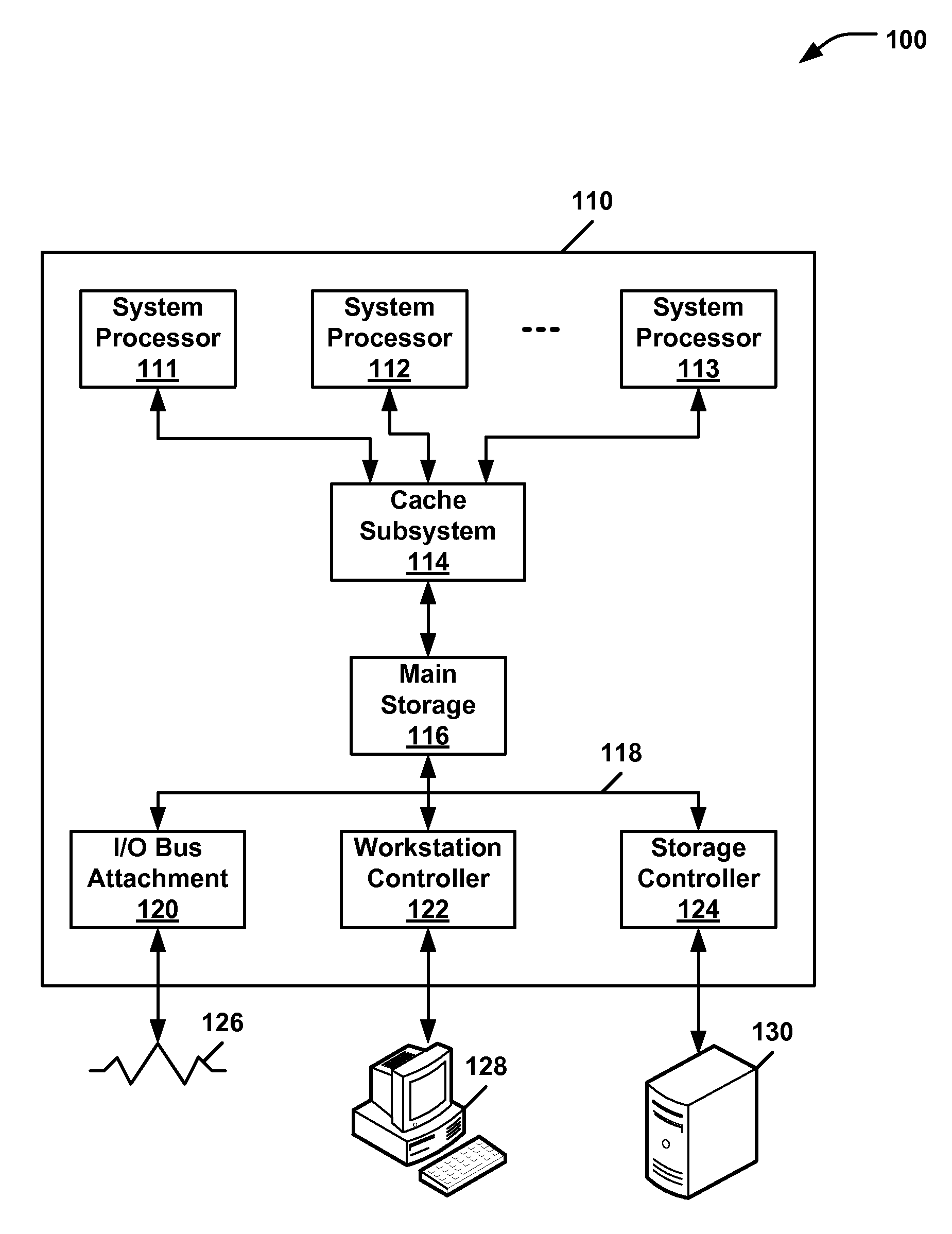
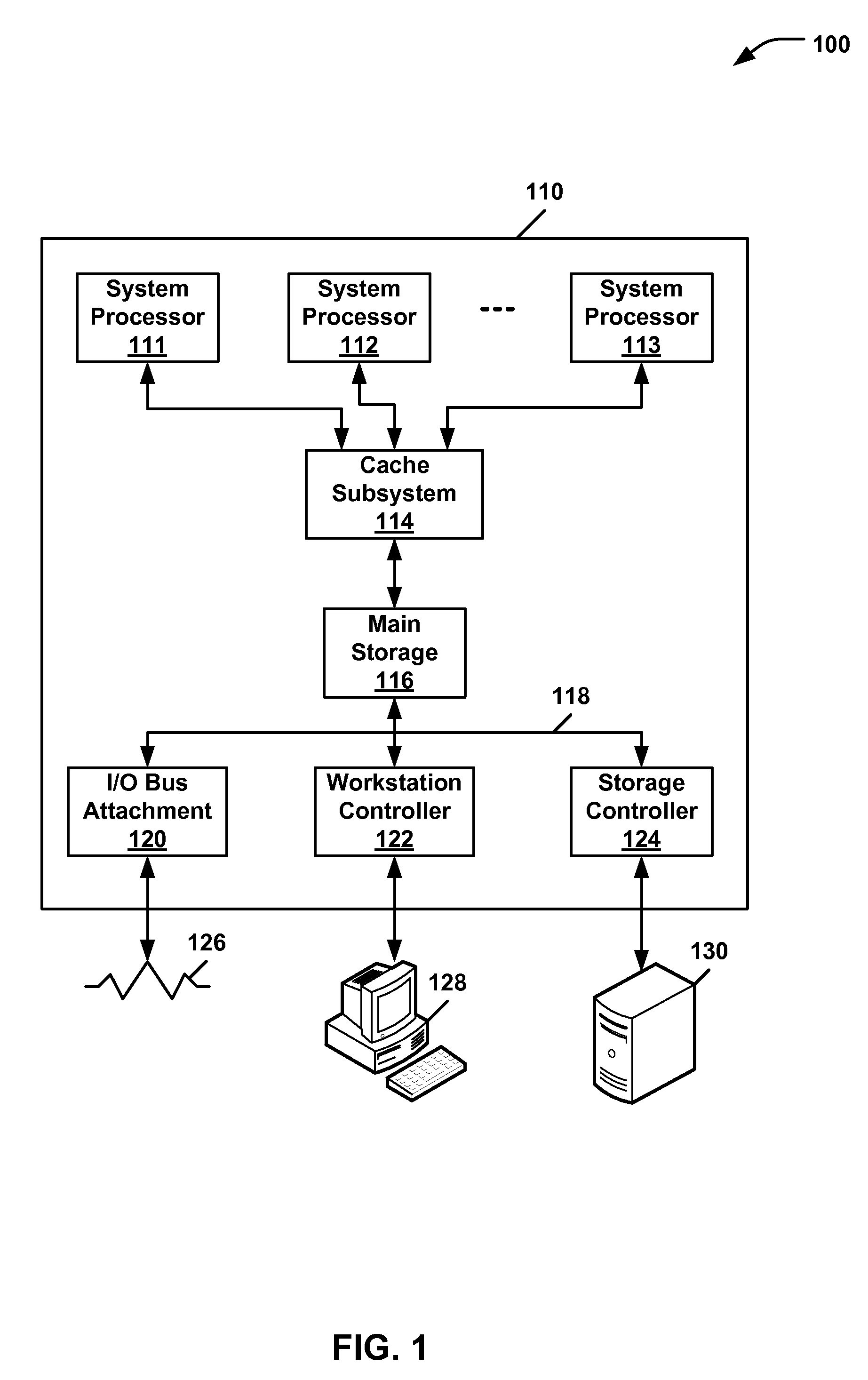
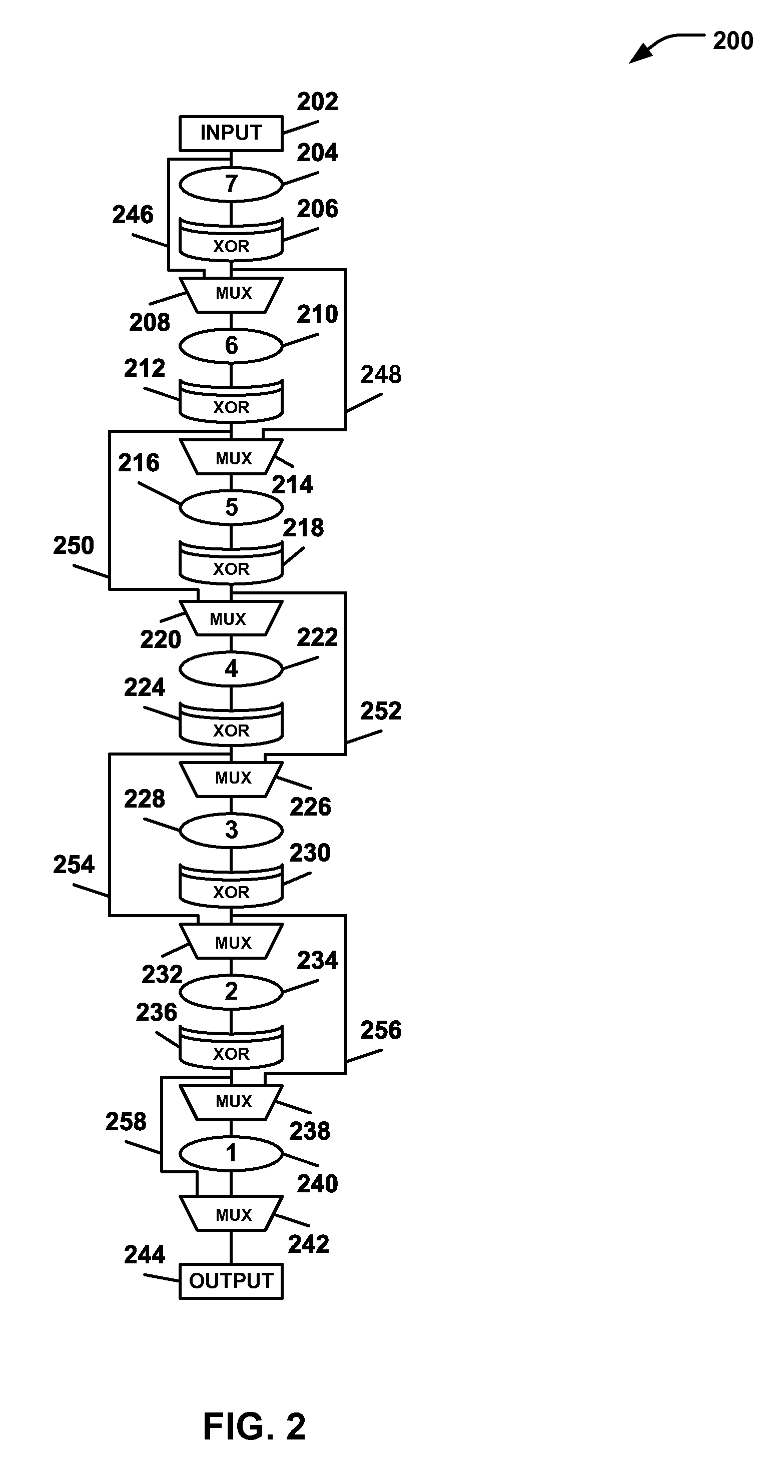
[0018]An embodiment of a system may identify and reduce fail data associated with testing an integrated circuit. Multiple bypass structures and injection points may be positioned for testing purposes within a scan chain comprising a plurality of latches, clocks, and associated connections. The injection points (e.g., XOR gates) and the bypass structures (e.g., multiplexers) may be used to find alternative paths that route around a component that is determined to be defective. Iterations of tests may be performed, and their results combined, to determine a functional status of other components in the scan chain that might otherwise be unknown.

[0019]A first test may include a full analysis of an entire scan chain. Subsequent tests may include partitioned paths of the scan chain. The XOR gates and the bypass multiplexers may be used to logically partition the scan chain into multiple sections, or paths. Multiple scan results may be iteratively combined to determine the functional statu...


PUM


Abstract

A method and apparatus are provided for isolating a defect in a scan chain comprising a plurality of components of an integrated circuit. A plurality of injection points may be positioned along the scan chain. Each injection point may be configured to introduce binary test data. A plurality of bypass structures may each be configured to selectively direct a flow of the binary test data to generate a plurality of partitioned scan paths. Test logic may be configured to execute a plurality of tests using the plurality of partitioned scan paths and to combine results of the plurality of tests to isolate a faulty component of the plurality of components.

Description

I. CROSS REFERENCE TO RELATED APPLICATIONS[0001]This application is a continuation application and claims priority from U.S. patent application Ser. No. 14 / 568,440, entitled “PARTITIONED SCAN CHAIN DIAGNOSTICS USING MULTIPLE BYPASS STRUCTURES AND INJECTION POINTS,” filed on Dec. 12, 2014, which is incorporated herein in its entirety.II. FIELD OF THE DISCLOSURE[0002]The present disclosure relates generally to the design of circuits of integrated circuits, and more particularly, to testing integrated circuits for fault isolation.III. BACKGROUND[0003]A circuit design may include a plurality of latches, such as shift register latches (SRLs), which are catenated to form a level sensitive scan design (LSSD) scan chain. As a part of quality control, patterns of logic “0” and logic “1” may be shifted into scan chains to observe an output of a scan chain under test. Because the circuitry of the scan chain is wired in series, a fault encountered in the scan chain can obscure downstream determ...

Claims


Application Information

Patent Timeline
Patent Type & Authority Patents(United States)
IPC IPC(8): G01R31/3177G06F11/25G06F7/02G01R31/3185G06F11/00
CPCG01R31/318583G01R31/318563
Inventor DOUSKEY, STEVEN M.HAMILTON, MICHAEL J.KAUFER, AMANDA R.
Owner INT BUSINESS MASCH CORP
Learn More