
Data reading method and storage device

a data reading and data technology, applied in the direction of maintaining head carrier alignment, digital signal error detection/correction, instruments, etc., can solve the problems of affecting the inability to detect such a failure, and the inability to read old data in time, so as to improve the reliability of the system, improve the reliability of the storage device, and read easily

Inactive Publication Date: 2008-04-24
TOSHIBA STORAGE DEVICE CORP
View PDF10 Cites 0 Cited by
  • Summary
  • Abstract
  • Description
  • Claims
  • Application Information

AI Technical Summary

Benefits of technology

[0011]Therefore, when data is read on a certain sector, it is possible to verify whether different read data exists on the same sector and thereby reliability of the data obtained can be improved.
[0014]According to the present invention, only the latest correct data can be read easily even when a plurality of data are written in a readable state on the same sector of the same track. Thereby, reliability of the storage device can be further improved.
[0015]Therefore, since undesirable events due to failure generated in the data can be avoided, the present invention can improve reliability for the system as a whole where the storage device of the present invention is used.

Problems solved by technology

However, it takes some amount of time to detect such a failure, and data may be written until the write process is suspended.
Accordingly, if the data width required by the read head is still left, the old data may sometimes be read erroneously, if the head is positioned on the old preceding data during the subsequent data read operation.
Therefore, even though the amount of offset is acceptable and allows for correct positioning of the head on the data, irregularity is found in the data, or a serious event such as system failure is likely generated, if erroneous old data read out by positioning the head thereto is transmitted to a host apparatus.

Method used


Image

  • Data reading method and storage device
  • Data reading method and storage device
  • Data reading method and storage device

Examples


first embodiment

[0048]As explained above, the correct data can be read even when a plurality of readable data exists on the same sector of the same track and thereby various system failures resulting from defective data can be avoided.

second embodiment

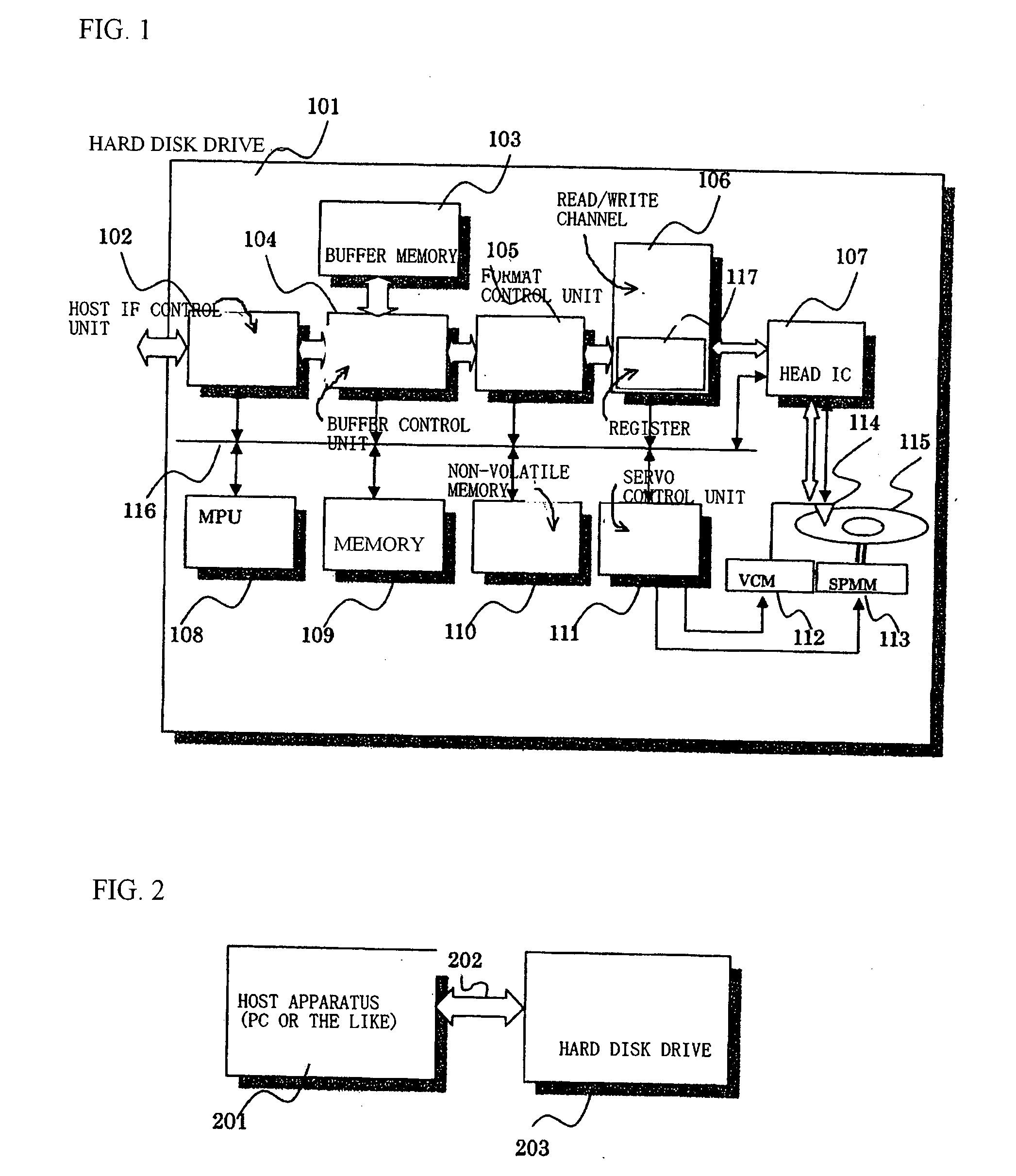
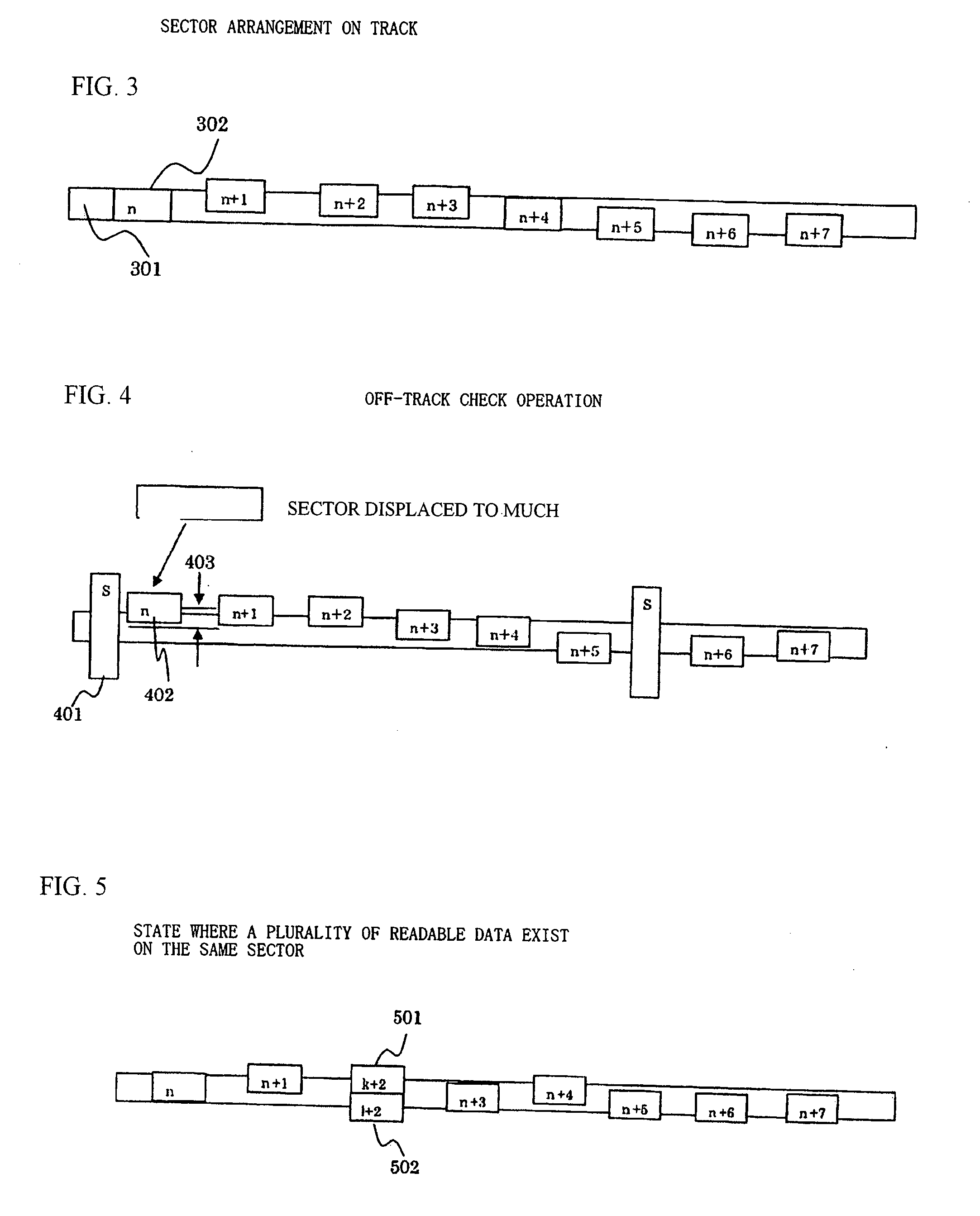
[0049]FIG. 8 is the present invention in which old data 802 and new data 803 are written with a certain displacement on the same sector of the same track 801 and the off-track state of data on a sector 805 just preceding the sector 806 explained above are indicated. The AGC values taken along line 804 are similar to those taken along line 604 in FIG. 6.

[0050]In this embodiment, the new and old data can be judged more accurately by judging the new and old data on the basis of the first embodiment explained above, and by also conducting the determination process using the off-track state of the data on the sector 805 just preceding the sector 806 explained above.

[0051]Namely, the new data 803 can be identified more accurately by utilizing the characteristic that when a defective data write process is detected on a certain sector during a continuous data write process on the track, the just preceding data may also be written with a certain amount of track offset on the same side of the...


PUM

PropertyMeasurementUnit
widthaaaaaaaaaa
distanceaaaaaaaaaa
lengthsaaaaaaaaaa

Abstract

A disk drive correctly recognizes newly written data when a plurality of readable data exist on the same sector of the same track, by comparing AGC values of each of the readable data, comparing error rates generated by Viterbi decoding, or both. An offset value determining means determines whether an offset value when the data is read has exceeded a predetermined value when the data is read. An offset control means controls the head, on the basis of the determination result of the offset value determining means, to conduct the offset operation on the opposite side of the track when the data is read the first time, and a selecting means selects the new data recorded in the sector by comparing the results obtained for both sets of data.

Description

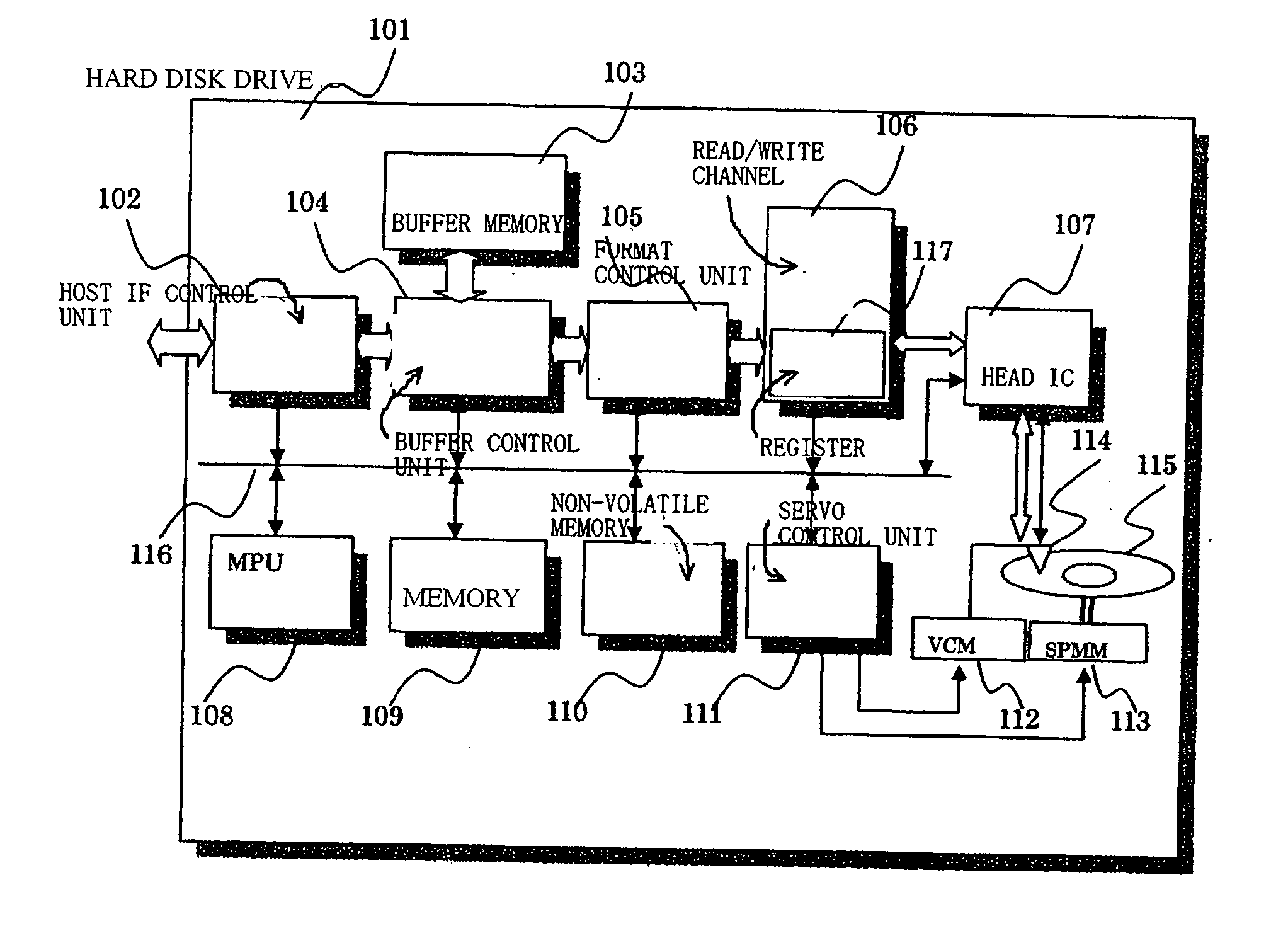
FIELD OF THE INVENTION[0001]The present invention relates to a data reading method for storage devices such as a hard disk drive, and more specifically to a data reading method and a storage device suitable for reading data written when the head is deviated from the center position of a track due to external influences such as vibration or the like.BACKGROUND OF THE INVENTION[0002]In a hard disk drive, the data transferred from a host apparatus is stored and read. The data is divided into predetermined data lengths (each called a sector), in regions of tracks formed in rings, each track having a predetermined width on a storage medium.[0003]If external factors such as vibration, shock or the like do not occur during the write process, the data is stored in alignment with the center in the width direction of the track. However, if an external factor such as vibration is generated, data is stored in a position deviated from the center of the track (FIG. 3).[0004]To correctly read data...

Claims


Application Information

Patent Timeline
Patent Type & Authority Applications(United States)
IPC IPC(8): G11B5/596
CPCG11B5/59627G11B19/045G11B20/10009G11B2220/2516G11B2020/1232G11B2020/1238G11B20/18
Inventor YOSHIDA, OSAMU
Owner TOSHIBA STORAGE DEVICE CORP
Learn More