Ultra fine pitch wedge for thicker wire

a wire thickness and ultra-fine technology, applied in the direction of manufacturing tools, basic electric elements, electric devices, etc., can solve the problems of affecting the performance and reliability of the device, the deformation caused by ball bonding requires a much larger pitch, and the limit of ball bonding

Inactive Publication Date: 2017-01-10
MICRO POINT PRO
View PDF13 Cites 3 Cited by
  • Summary
  • Abstract
  • Description
  • Claims
  • Application Information

AI Technical Summary

Benefits of technology

[0012]Embodiments disclosed herein enable wire bonding for devices with ultra-fine pitch. In order to enable the ultra-fine pitch, embodiments of the invention provide a tip size with higher accuracy and gripping, which isn't available in the prior art. An oval hole is provided for the wire, having a special shape which complies with new clearance consideration. Since the thick wire is a design barrier on the wire exit, a special pocket is designed on the wedge's lower part. Also a new material is used so as to provide higher strength. Finally, an accurate wedge manufacturing process is used. This ultra-fine pitch wedge, in conjunction with bonder advances, have significantly improved bond placement thus enabling achieving the finest pitch available for any wire bonding process.
[0018]According to yet further embodiments, the wedge bonding tool has a foot section that is formed to have curvature corresponding to the wire on the bonding surface. This helps maintain the wire aligned to the bonding foot.

Problems solved by technology

However, as the need for much denser interconnects is increasing (the ITRS roadmap predicts that we are heading towards 20 μm pitch), ball bonding is reaching its limits.
Notably, the deformation caused by ball bonding requires much larger pitch than that is required by wedge bonding.
Many new devices require more current flow and the smaller diameter wire required by finer pitch devices has a negative impact on performance and reliability of the device.
First, the ability to locate the wedge tip exactly on the desired location, including the ability to perform complicated processes.

Method used


Image

  • Ultra fine pitch wedge for thicker wire
  • Ultra fine pitch wedge for thicker wire
  • Ultra fine pitch wedge for thicker wire

Examples


example i

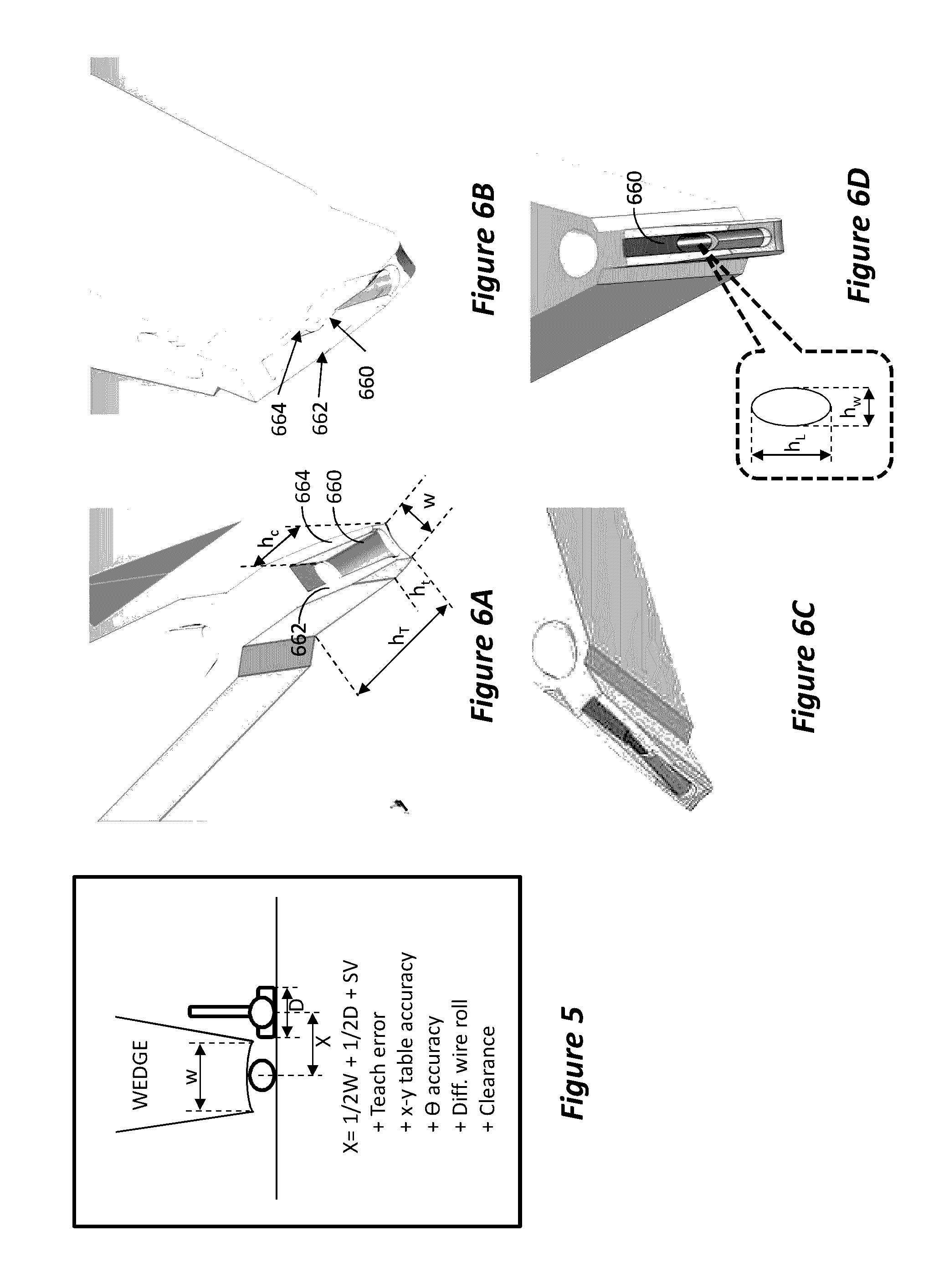
[0037]A wedge tool was designed for ultra-fine wire pitch of 35 microns. With reference to FIG. 5, the following calculations are done in order to create a theoretical design, based on the application data. FIG. 5 illustrates the factors to be considered for final wedge width, W.

Variables:

[0038]WD⁡(Wire⁢⁢Diameter)=20⁢⁢μmd⁡(bond⁢⁢deformation)=22⁢%SV⁡(Squash⁢⁢Variation)=1⁢⁢μmD⁡(Squash⁢⁢Width)=WD×(100+d)100D⁡(Squash⁢⁢Width)=20×(100+22)100D⁡(Squash⁢⁢Width)=24.4⁢⁢μm_

Source of Error:

[0039]T⁡(Teach⁢⁢Error)=1⁢⁢μmTa⁡(X⁢-⁢Y⁢⁢Table⁢⁢Accuracy)=0.5⁢⁢μmΘ⁡(Theta⁢⁢Accuracy)=0⁢⁢μmWr⁡(Wire⁢⁢Roll⁢⁢under⁢⁢the⁢⁢wedge)=0⁢⁢μmC⁡(Clearance)=0⁢⁢μmX⁡(Pad,Wire⁢⁢Pitch)=35⁢⁢μmX=(W+D)2+Sv+T+Ta+θ+Wr+C(W+D)2=X-(Sv+T+Ta+θ+Wr+C)W⁡(Wedge⁢⁢Width)=2×[X-(Sv+T+Ta+θ+Wr+C)]-DW⁡(Wedge⁢⁢Width)=2×[35-(1+1+0.5+0+0+0)]-24.4W⁡(Wedge⁢⁢Width)=40.6⁢⁢μm⁡(1.6⁢⁢mil)_

[0040]Therefore, according to this example, the new 35 μm wedge tool includes the following features. The wedge has narrow front wedge width of 1.6 mil (40.6 μm) to keep th...

example ii

[0051]FIGS. 6A-6D illustrate various views of the tip of a wedge tool designed according to the above parameters and suitable for ultra-fine wire pitch, such as 35 microns. FIGS. 7A-7C are illustration of front (leading) edge, side, and rear (wire-feeding edge) views, respectively, of the designed wedge tool according to this example. The design of this example is configured to conform to two opposing requirements, namely, be very thin so as to enable placing between wires bonded at ultra-fine pitch and at the same time have wide hole enabling the threading of a large diameter wire—without the hole weakening the tip of the wedge tool. As illustrated in FIGS. 7A-7C, much of the upper part of the wedge tool is an elongated block the design of which is not relevant to the design or operation of the tool, it is therefore illustrated as truncated and is referred to herein as main body. The lower part of the wedge tool undergoes tapering by several tapered sections, culminating in a foot ...

example iii

[0059]A method for fabricating an ultra-fine pitch wedge tool has been developed. The method starts by obtaining a substantially rectangular slab of a tungsten carbide alloy having grain size of 0.5 μm or smaller, density above 14.5 g / cm3, hardness higher than 90 HRa or 2,000 HV30, and transverse rupture strength higher than 400 KPSI. The slab is machined to form a main body part, a tapered part reducing the width of the main body part towards a tip part, and a tip part extending from the tapered part and terminating at the bottom of the tool to form a bonding foot. The tip part is further machined to have a tip tapered part, so as to reduce the width of the tip such that the foot has the smallest width, Wt, of the wedge tool. The width Wt is calculated to enable bonding wires at ultra-fine pitch, i.e., pitch of 35 μm or less.

[0060]In order to enable the use of a thick wire, a pocket 660 is formed at the bottom of the tip, behind the bonding foot. The pocket extends from the bottom ...


PUM

PropertyMeasurementUnit
acute angleaaaaaaaaaa
grain sizeaaaaaaaaaa
densityaaaaaaaaaa

Abstract

An ultra-fine pitch wedge bonding tool and method for its manufacture are disclosed. The wedge tool is formed with a foot width calculated to enable accurate bonding of wires separated at an ultra-fine pitch. The wedge tool is made out of a tungsten carbide alloy having characteristics conforming to specified constraints that lead to improved performance and enable the use of thicker wire. A pocket is formed at the tip of the wedge tool and a wire feeding hole is formed from the rear side of the tool and exiting inside the pocket, at an elevation above the bonding foot. Side walls are provided on both sides of the pocket to guide the wire exiting the feed hole inside the pocket towards the bonding foot.

Description

RELATED APPLICATION[0001]This application is a continuation of and claims priority from U.S. Provisional Application Ser. No. 61 / 755,464, filed on Jan. 22, 2013, the disclosure of which is incorporated herein by reference in its entirety.BACKGROUND[0002]1. Field[0003]This invention relates to wedge tool for welding fine wires in the semiconductor chip industry. More particularly, the present invention relates to a wire bonding method and apparatus that enables welding wires to bonding pads positioned at an ultra-fine pitch.[0004]2. Related Arts[0005]Wire bonding is used in a semiconductor industry to electrically connect a chip to the circuit board. A plurality of bonding pads are located in a pattern on the top surface of the board, with the chip mounted in the center of the pattern of bonding pads. In standard chips, i.e., non-flip chip, the top surface of the chip facing away from the top surface of the substrate has a plurality of contact pads. Fine wires (which may be aluminum ...

Claims


Application Information

Patent Timeline
Patent Type & Authority Patents(United States)
IPC IPC(8): B23K31/02H01L23/00
CPCH01L24/78H01L24/45H01L2224/45015H01L2224/45144H01L2224/78315H01L2224/78318H01L2224/78319H01L2924/00014H01L2924/381Y10T29/49995H01L2924/20752H01L2924/20751H01L2224/45099H01L2924/00
Inventor ZAKS, URIVOSKOBOYNIKOV, IRINAPROSSO, YEFIMSASTIEL, IRINA
Owner MICRO POINT PRO
Why Eureka
Try Eureka