
Image forming apparatus having scanning optical device

a technology of scanning optical device and image forming apparatus, which is applied in the direction of electrographic process apparatus, optics, instruments, etc., can solve the problems of image failure in which a fine striped pattern is printed, image deformation, jitter or banding, etc., to reduce the amount of heat generation of the deflector, reduce the amount of deflector heat generation, and facilitate the control of scanning displacemen

Active Publication Date: 2017-01-10
KYOCERA DOCUMENT SOLUTIONS INC
View PDF17 Cites 0 Cited by
  • Summary
  • Abstract
  • Description
  • Claims
  • Application Information

AI Technical Summary

Benefits of technology

The present invention aims to restrict optical box thermal deformation in an image forming apparatus. This is achieved by reducing heat generation from the deflector and scanning optical device, which results in improved control of scanning displacement. Additionally, the invention reduces vibration caused by the rotation of the deflector. Thus, it provides an image forming apparatus with improved performance and stability.

Problems solved by technology

If the optical box may be thermally deformed, since positions of the optical components vary, a displacement in a main scanning direction and in a sub scanning direction occurs, causing degraded scanning precision.
Also, there is a problem that there may occur an image failure in which a fine striped pattern is printed, such as jitter or banding, due to rotary vibration exerted by a high speed rotation of the deflector (for example, 50,000 rpm).

Method used


Image

  • Image forming apparatus having scanning optical device
  • Image forming apparatus having scanning optical device
  • Image forming apparatus having scanning optical device

Examples


first embodiment

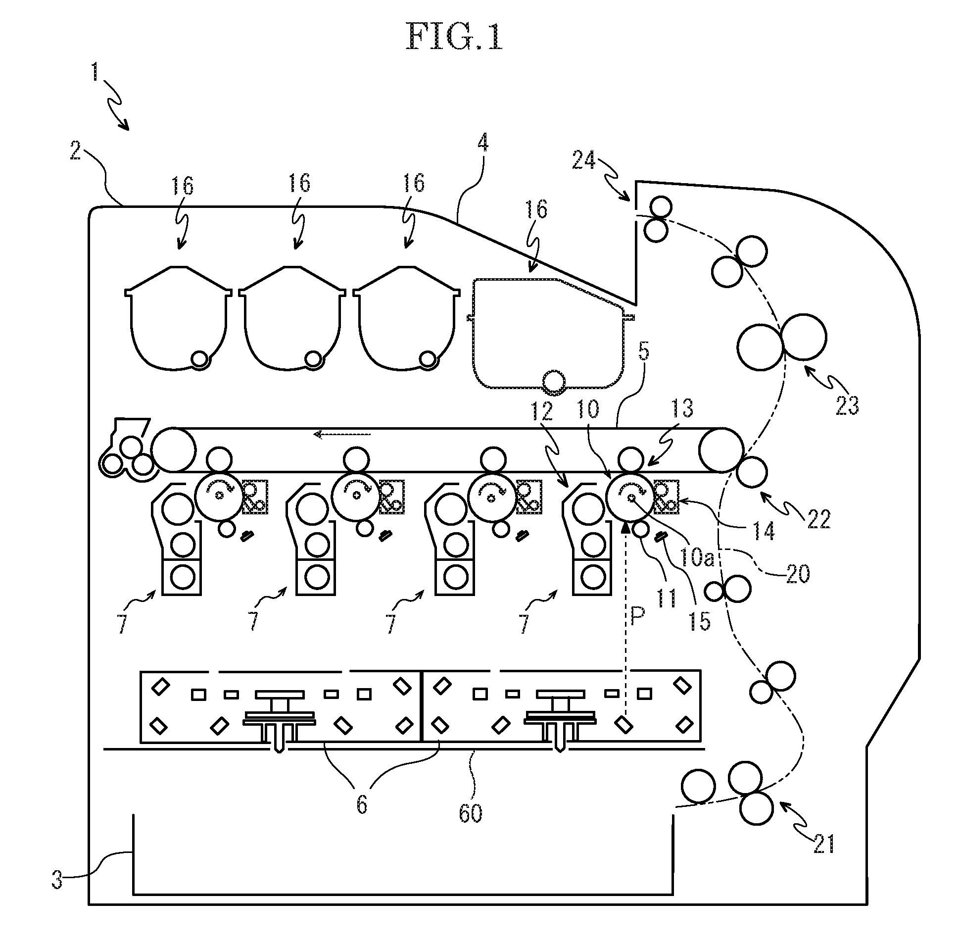
[0023]First, with reference to FIG. 1, the entire structure of a color printer 1 as an example of an electrographic image forming apparatus will be described. FIG. 1 is a schematic diagram schematically showing a color printer according to one embodiment of the present disclosure. In the following description, a left side in FIG. 1 shows a front side of the printer 1 and directions perpendicular to the forward and rearward directions seen from the front side show left and right directions.

[0024]The color printer 1 includes a box-like formed printer main body 2, a sheet feeding cassette 3 storing sheets (not shown) is provided in a lower part of the printer main body 2 and an ejected sheet tray 4 is formed on an upper end of the printer main body 2.

[0025]In an upper part of the printer main body 2, an intermediate transferring belt 5 is bridged between a plurality of rollers, and under the intermediate transferring belt 5, two scanning optical devices 6 each composing of a laser scan...

second embodiment

[0059]Next, a scanning optical device of a color printer as an image forming apparatus according to a second embodiment of the present invention will be described with reference to FIGS. 5 to 6. FIG. 5 is a perspective view showing a scanning optical device and a frame and FIG. 6 is a sectional side view of the scanning optical device.

[0060]Two scanning optical devices 100, as shown in FIG. 5 (only one is shown in FIG. 5), are mounted side by side in the forward and rearward directions to a frame 101 extending in the forward and rearward directions under the image forming parts 7 in the printer main body 2 (refer to FIG. 1).

[0061]The scanning optical device 100, as shown in FIG. 6, has two light sources (not shown), a deflector 30, a heat sink 36, a pair of optical components groups 40, and an optical box 102 in which the light sources and the deflector 30, the heat sink 36, and the pair of optical components groups 40 are housed. The light sources, the heat sink 36, the deflector 3...


PUM


Abstract

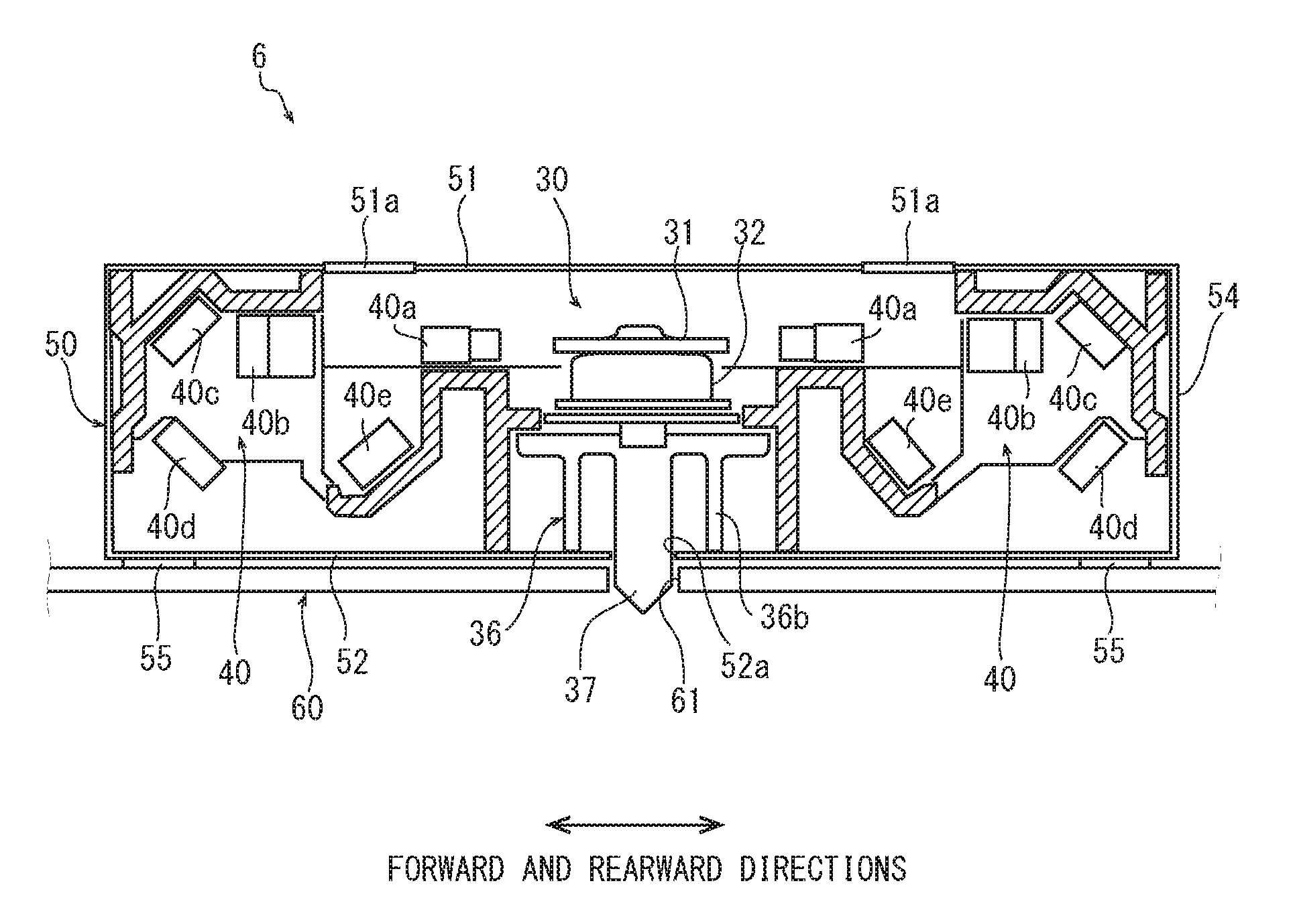
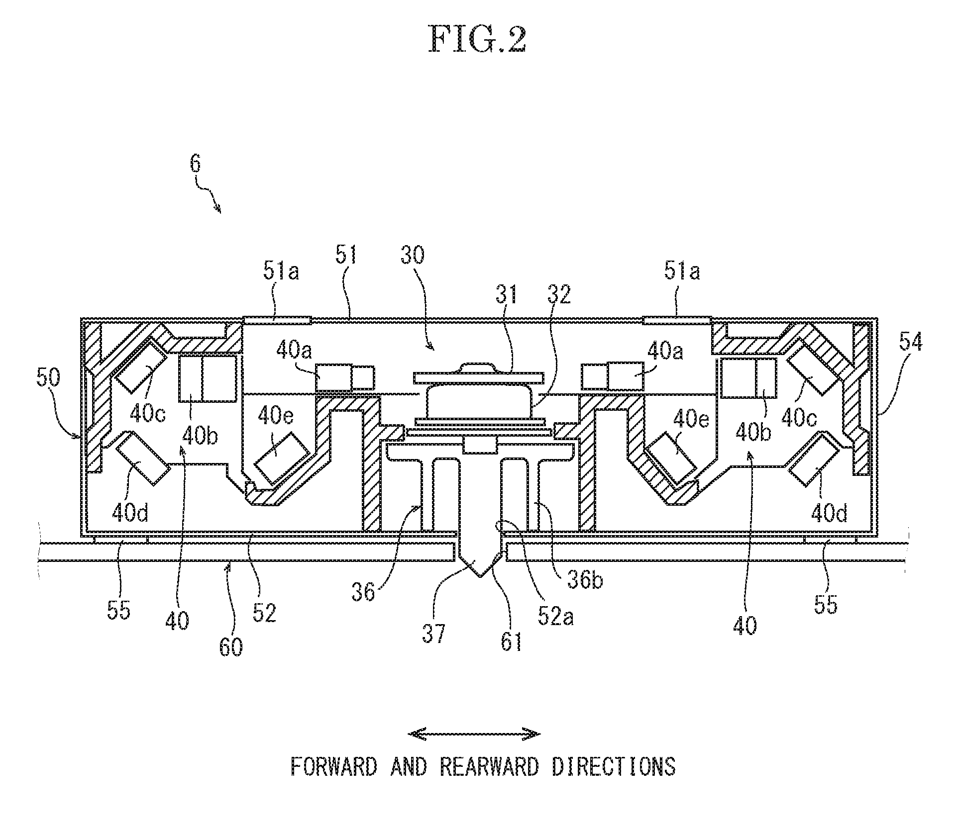
The scanning optical device (6) includes a light source, a deflector (30) configured to rotate on a horizontal surface around a rotating shaft extending in a vertical direction and an optical box (50) in which the light source, the deflector (30), and the optical components groups (40) are housed and supported by the frame (60). A heat sink (36) is disposed between the deflector (30) and the frame (60). A first protrusion (37) extending on an extension line of the rotating shaft of the deflector (30) is formed in the heat sink (36). A first engaging hole (61) with which the first protrusion (37) engages is formed in the frame (60).

Description

TECHNICAL FIELD[0001]The present invention relates to an image forming apparatus including a scanning optical device configured to scan and expose laser light to a photosensitive drum.BACKGROUND[0002]An image forming apparatus is provided with a scanning optical device composed of a laser scanning unit (LSU) exposing laser light to a photosensitive drum to form an electrostatic latent image. The scanning optical device includes: a light source which emits laser light; a deflector which deflects the laser light; and optical components groups such as a lens or a mirror. The light source, the deflector, and the optical components groups are housed in an optical box which is mounted to a frame of the image forming apparatus.[0003]The deflector has: a polygon mirror; a polygon motor which rotates and drives the polygon mirror; and the others. The optical box in which the deflector is housed is generally formed of a resin and is therefore easily thermally deformed by heating from the poly...

Claims


Application Information

Patent Timeline
Patent Type & Authority Patents(United States)
IPC IPC(8): G03G15/04H04N1/00G02B26/12H04N1/113G02B26/10G03G21/00G03G21/20
CPCG03G21/20G02B26/10G02B26/12G02B26/121G02B26/124G03G15/04G03G15/04036H04N1/00984H04N1/113G03G21/043
Inventor MASAKI, AKIHIRO
Owner KYOCERA DOCUMENT SOLUTIONS INC
Learn More