Device for inspecting a material provided with a coated surface and related method

a technology for coating surfaces and inspection devices, applied in the direction of material analysis, material testing goods, instruments, etc., can solve the problems of different colors of surfaces, high complexity and time-consuming, and the color of surfaces to no longer appear homogeneous, and achieve the effect of large viewing angle differences

Active Publication Date: 2017-01-03
ISRA SURFACE VISION
View PDF10 Cites 0 Cited by
  • Summary
  • Abstract
  • Description
  • Claims
  • Application Information

AI Technical Summary

Benefits of technology

[0009]The invention provides a device with which the color inspection of a material provided with a coated surface is carried out in a simple and cost-favorable manner and method for inspecting the color of coated surfaces though the use of such device.
[0041]As explained above, this embodiment makes it possible to obtain a large viewing angle difference since it is possible to use the color value of the camera having the minimum viewing angle and the color value of the camera having the maximum viewing angle for the comparison with the predefined color setpoint value or the color setpoint value range, for each point of the inspection line.

Problems solved by technology

Coated surfaces, in particular those having a plurality of layers, form interferences (interference layers), which cause the surfaces to exhibit different colors from different viewing angles.
When such materials having coated surfaces are produced, defects can occur that cause the color of the surface to no longer appear homogeneous.
This is highly complex and time-consuming, however, and it would be desirable to find a simpler and more cost-favorable solution for inspecting the color of coated surfaces.
Nowadays, high-quality surfaces, for example, glass that is used to build glass facades, are nearly always subjected to an optical inspection for these other defects.
The color information obtained from the reflected light is not required for the investigation of such defects, and therefore the optical recording devices used to detect such defects do not capture the color information.

Method used


Image

  • Device for inspecting a material provided with a coated surface and related method
  • Device for inspecting a material provided with a coated surface and related method
  • Device for inspecting a material provided with a coated surface and related method

Examples


Embodiment Construction

[0055]The following is a detailed description of example embodiments of the invention depicted in the accompanying drawings. The example embodiments are presented in such detail as to clearly communicate the invention and are designed to make such embodiments obvious to a person of ordinary skill in the art. However, the amount of detail offered is not intended to limit the anticipated variations of embodiments; on the contrary, the intention is to cover all modifications, equivalents, and alternatives falling within the spirit and scope of the present invention, as defined by the appended claims.

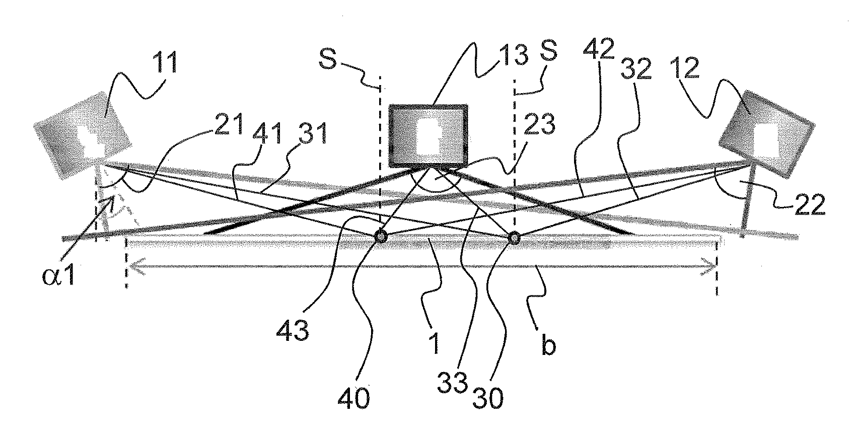
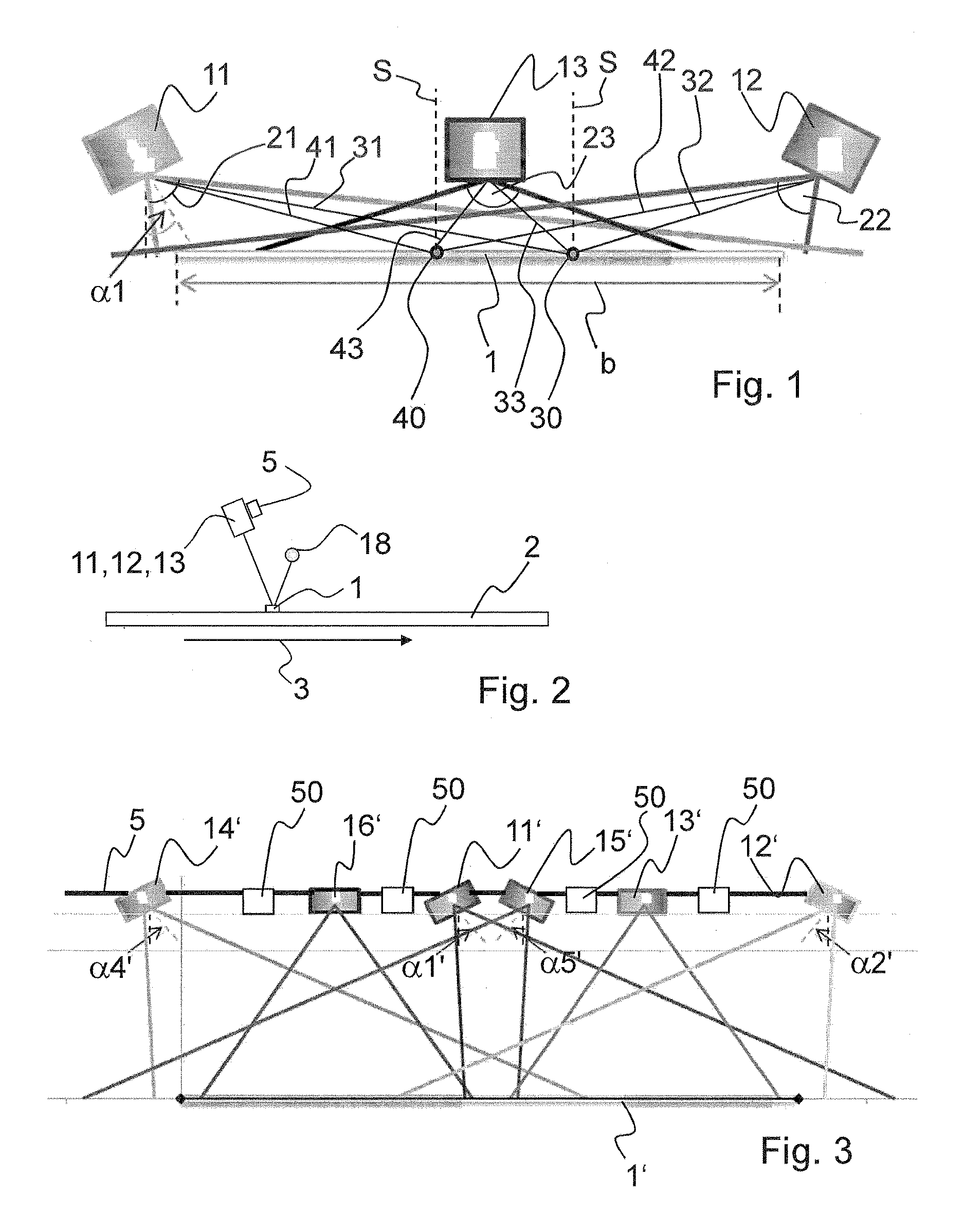
[0056]The device depicted in FIG. 1 shows the inspection line 1 on the surface of the material, which is shown in FIG. 2, in the form of a glass 2 provided with a surface coating (e.g., an antireflective coating or a thermal barrier coating) and which is observed by a first camera 11, a second camera 12, and a third camera 13. The material 2 is moved in the moving direction indicated by the...


PUM

PropertyMeasurementUnit
viewing angleaaaaaaaaaa
angle of inclinationaaaaaaaaaa

Abstract

A device for inspecting a material with a coated surface includes a light source disposed above the surface that emits light in a wavelength range, at least one first camera for determining a color value of detected light reflected from the surface and an evaluation device. The first camera is disposed above a line located on the surface and configured with a first aperture to detect light from a first point of the line at a first viewing angle and light from a second point separate from the first point at a second viewing angle. The first camera determines a first color value of the first point light and a second color value of the second point light and the evaluation device compares the first and second color values or a color value difference with a predefined color setpoint value or predefined color setpoint value range.

Description

CROSS-REFERENCE TO A RELATED APPLICATION[0001]The invention described and claimed hereinbelow is also described in German Patent Application DE 10 2014 100 594.5, filed on Jan. 20, 2014. The German Patent Application, the subject matters of which is incorporated herein by reference, provides the basis for a claim of priority of invention under 35 U.S.C. 119(a)-(d).BACKGROUND OF THE INVENTION[0002]The present invention relates to a device for inspecting a material provided with a coated surface, preferably glass, and a related method.[0003]Surface coatings on materials, in particular glass, are intended to improve or modify the properties of these materials, for example, as antireflective coatings or thermal barrier coatings. Surface coatings comprise thin metal layers or dielectric layers, for example. Coated surfaces, in particular those having a plurality of layers, form interferences (interference layers), which cause the surfaces to exhibit different colors from different viewin...

Claims


Application Information

Patent Timeline
Patent Type & Authority Patents(United States)
IPC IPC(8): G01J3/46G01N21/896G01N21/84G01N21/25G01J3/50
CPCG01N21/251G01J3/50G01N21/8422G01N21/896G01N2021/8427G01N2201/061G01J3/46G01N21/84G01N33/38
Inventor KUBIAK, ROLF
Owner ISRA SURFACE VISION
Why Eureka
Try Eureka