Method for Measuring the Phase Jitter of a High-Frequency Signal and a Measuring Device for the Implementation of This Method

a high-frequency signal and phase jitter technology, applied in measurement devices, instruments, special data processing applications, etc., can solve the problems of affecting the accuracy of the signal, the inability of the classic spectrum analyzer to distinguish between am and fm modulation, and the relative complexity of the known measuring station of this kind. the effect of cost and convenien

Active Publication Date: 2008-04-24
ROHDE & SCHWARZ GMBH & CO KG
View PDF5 Cites 4 Cited by
  • Summary
  • Abstract
  • Description
  • Claims
  • Application Information

AI Technical Summary

Benefits of technology

[0005]There exists a need for providing a simple method, according to which a phase-jitter measurement can be implemented using a conventional spectrum analyzer with a quality, which has hitherto only been possible with expensive measuring stations. A further aspect of an embodiment of the present invention is to provide a simple and cost-favorable measuring device for the implementation of a method of this kind.

Problems solved by technology

Measuring the phase jitter of a high-frequency signal, for example, the output signal of an oscillator, has hitherto generally required a measuring station, which consists of several individual devices, which are relatively expensive and difficult to operate.
A known measuring station of this kind is therefore relatively complex, expensive and difficult to operate.
However, the classic spectrum analyzer cannot distinguish between AM and FM modulation, although, generally, only the FM component needs to be measured.
With modern spectrum analyzers with digital evaluation of the last intermediate frequency, the AM and FM modulation can in fact be measured separately, but the dynamic range of the analog / digital converter used is not sufficient for the measurement of good low-noise oscillators.

Method used


Image

  • Method for Measuring the Phase Jitter of a High-Frequency Signal and a Measuring Device for the Implementation of This Method
  • Method for Measuring the Phase Jitter of a High-Frequency Signal and a Measuring Device for the Implementation of This Method

Examples


Embodiment Construction

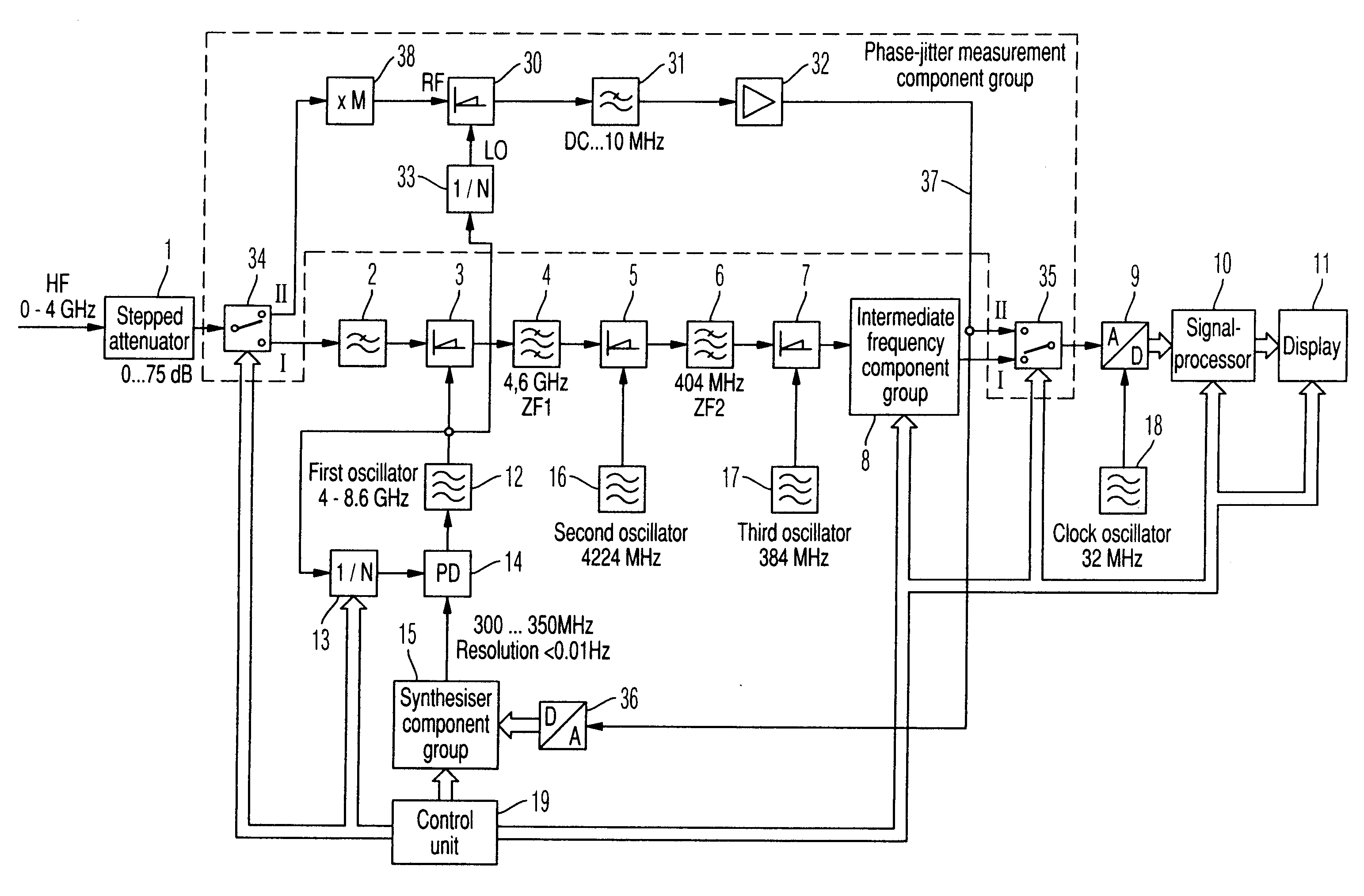
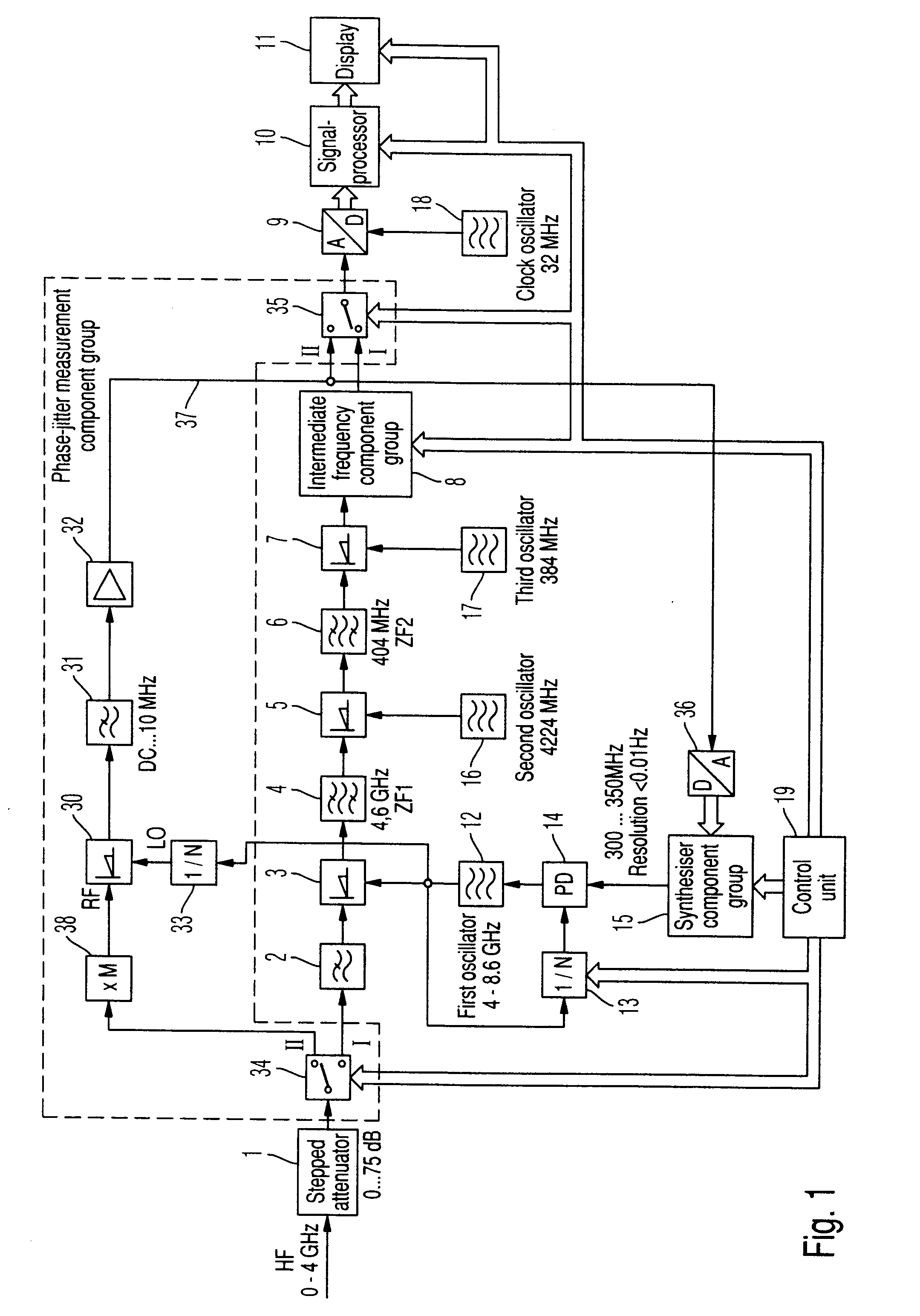
[0015]The individual component groups of the spectrum analyzer are indicated in FIG. 1 with the reference numbers 1 to 19. The additional component groups, by means of which this spectrum analyzer is expanded to provide a measuring device for measuring phase jitter, are indicated with reference numbers greater than 30.

[0016]When operating the measuring device as a spectrum analyzer, the high-frequency input signal HF is supplied via a variable attenuator 1 and the input switching unit 34 occupying the switching position I to the input low-pass filter 2 and from there to the input mixer 3. The input low-pass filter 2 ensures an unambiguous imaging of the input signal, because the first intermediate frequency ZF1 is disposed above the input frequency range. The first frequency conversion in the input mixer 3 is implemented with the output frequency of a phase-controlled oscillator 12, of which the output frequency, divided in a controlled frequency divider 13, is synchronised in a pha...


PUM


Abstract

In order to measure the phase jitter of a high-frequency signal, a spectrum analyzer is used. The high-frequency signal (HF) to be measured is either multiplied by M and/or the output frequency of the variable frequency oscillator of the spectrum analyzer is divided by N, and both signals are set to the same frequency and mixed in a mixer. The output signal of the mixer is then evaluated in the preferably digital evaluating device of the spectrum analyzer according to the Fast Fourier Transformation principle. To this end, the spectrum analyzer requires only one additional mixer, frequency divider and/or frequency multiplier.

Description

FIELD OF THE INVENTION[0001]The invention, according to various embodiments, relates to measuring the phase jitter of a high-frequency signal using a spectrum analyzer.BACKGROUND OF THE INVENTION[0002]Measuring the phase jitter of a high-frequency signal, for example, the output signal of an oscillator, has hitherto generally required a measuring station, which consists of several individual devices, which are relatively expensive and difficult to operate. These are generally a signal generator, a spectrum analyzer for low-frequency Fast-Fourier Transform (FFT), a control computer and a supplementary mixer. To measure the phase jitter, the high-frequency signal to be measured is mixed with a comparison signal of the same frequency generated in the signal generator. The mixer then supplies an output signal, which is the differential frequency between the high-frequency signal to be measured and the comparison signal. This therefore presents a measure for the phase jitter. This differ...

Claims


Application Information

Patent Timeline
Patent Type & Authority Applications(United States)
IPC IPC(8): G01R29/26
CPCG01R29/26
Inventor ROTH, ALEXANDER
Owner ROHDE & SCHWARZ GMBH & CO KG
Why Eureka
Try Eureka