
Single sided continuous optoelectrowetting (SCEOW) device for droplet manipulation with light patterns

Active Publication Date: 2017-01-03
RGT UNIV OF CALIFORNIA
View PDF12 Cites 7 Cited by
  • Summary
  • Abstract
  • Description
  • Claims
  • Application Information

AI Technical Summary

Benefits of technology

This patent describes a new technology for manipulating droplets of liquid on a surface using light patterns. This technology allows for the continuous movement, mixing, and manipulation of droplets, regardless of their size. The technology is flexible and can be easily integrated with other microfluidic components. The technology also requires low light intensity to activate and can be controlled using a display screen. Overall, this new technology provides a more efficient and flexible tool for manipulating droplets in microfluidic systems.

Problems solved by technology

However, the thick amorphous silicon layer used in COEW for matching the electrical impedance of the dielectric layer is difficult to reproduce due to large residual stress during the deposition process.
Large voltage leaks in areas not covered by droplets also resulted in droplet instability issues while satellite droplets ejected from mother droplets were often observed during experiments.

Method used


Image

  • Single sided continuous optoelectrowetting (SCEOW) device for droplet manipulation with light patterns
  • Single sided continuous optoelectrowetting (SCEOW) device for droplet manipulation with light patterns
  • Single sided continuous optoelectrowetting (SCEOW) device for droplet manipulation with light patterns

Examples


embodiment 10

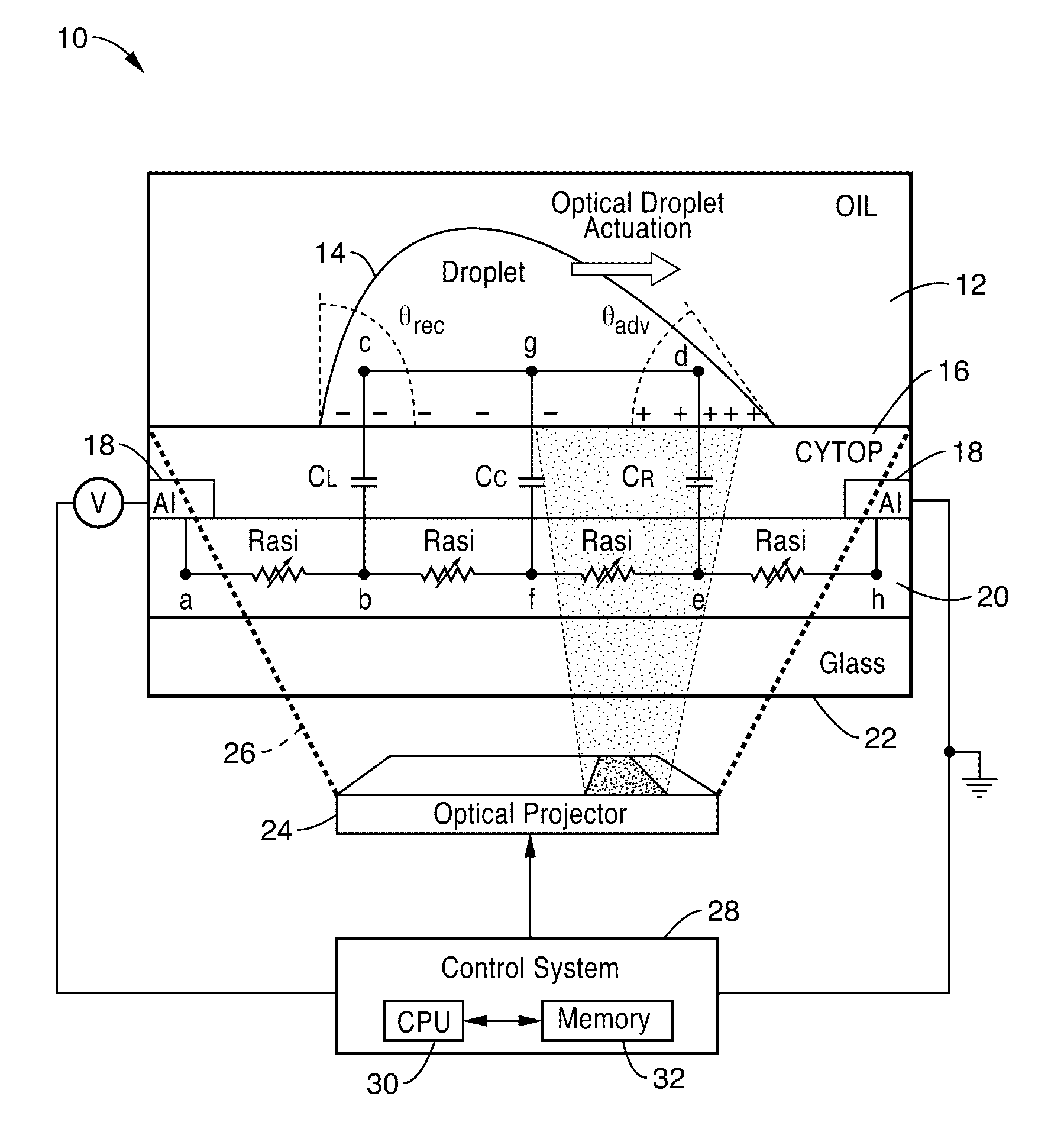
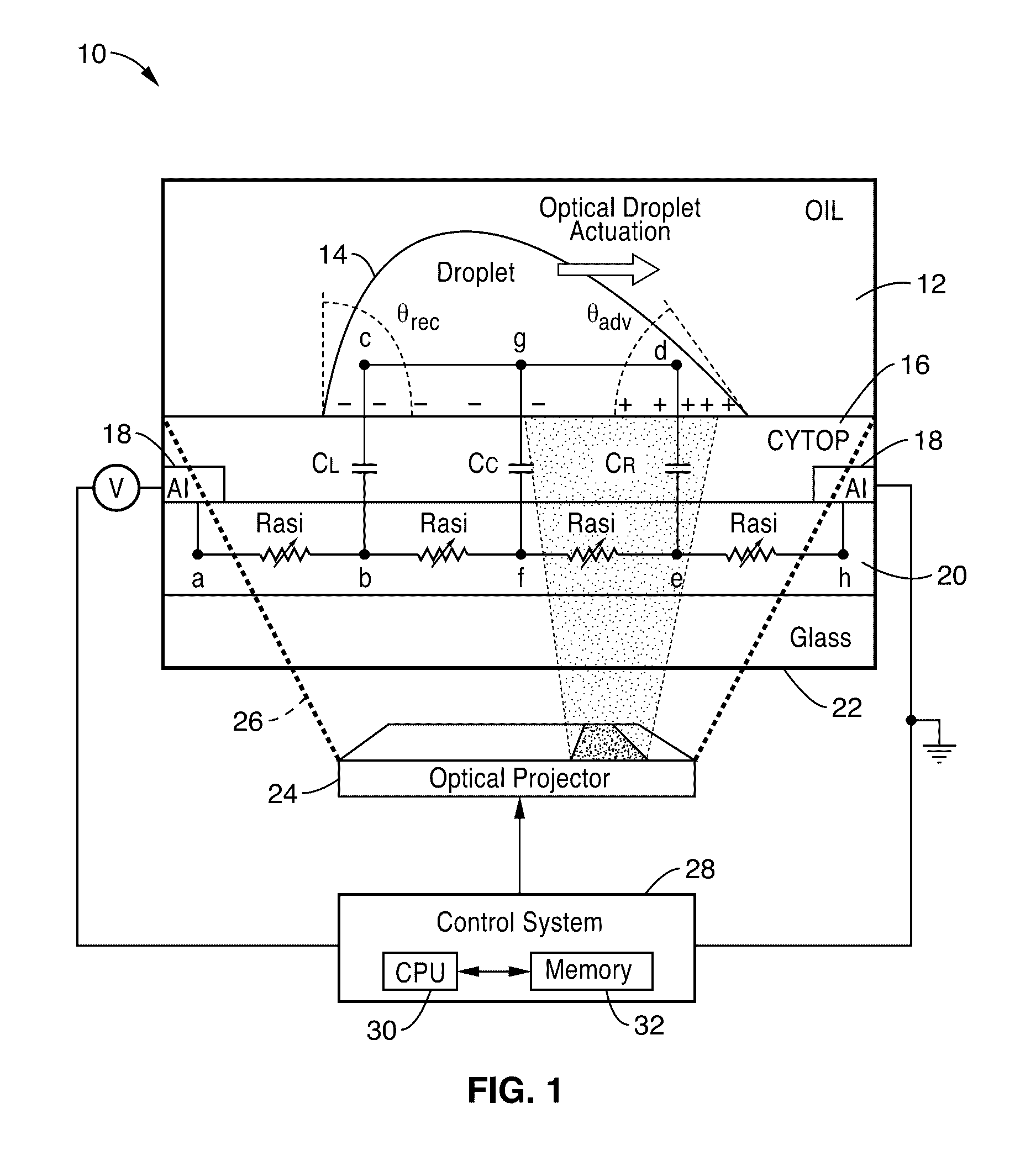
[0031]FIG. 1 illustrates an embodiment 10 of our inventive SCOEW device, and its equivalent circuit model, for directing aqueous droplets of a second fluid 14 within a first fluid (e.g., oil) wetting a dielectric layer 16, disposed over electrodes 18 and a photoconductive layer 20. The embodiment is shown by way of example implemented over a glass substrate 22.

[0032]The photoconductive layer 20 preferably comprises a semiconductor layer, such as 0.5 μm thick featureless hydrogenated amorphous silicon (a-Si:H) layer. Electrodes 18 are disposed laterally, along the plane of photoconductive layer 20, to provide a lateral electrical field in response to receiving a DC bias, and not for directing the direction of droplet transport. In the example embodiment, the electrodes 18 comprise two 0.1 μm thick strip aluminum (Al) electrodes separated by a 5 cm gap deposited at two ends of this device. A DC bias is shown applied to the two aluminum electrodes to provide a lateral electric field ac...

embodiment 1

[0070]2. The apparatus of embodiment 1, wherein photoconductivity differs by a factor of two between illuminated and non-illuminated areas.

[0071]3. The apparatus of embodiment 1, wherein said local voltage drop comprises voltage differences between the top and bottom surfaces of the hydrophobic dielectric layer in response to said illumination.

[0072]4. The apparatus of embodiment 1, wherein said voltage source comprises a direct current (DC) bias voltage at or exceeding approximately 100 volts.

[0073]5. The apparatus of embodiment 1, wherein the contact angle of the droplet is determined by the local voltage drop across said hydrophobic dielectric layer between the droplet and the underlying electrodes as given by

[0074]cos⁢⁢θ=cos⁢⁢θ0+12⁢γ⁢cV2,

in which c is specific capacitance, γ is surface tension between the droplet and surrounding medium, and V is voltage drop across a dielectric layer in the vertical direction at a three-phase contact line, with θ0 and θ representing the droplet ...

embodiment 7

[0077]8. The apparatus of embodiment 7, wherein said hydrogenated semiconductor layer comprises a hydrogenated amorphous silicon layer.

[0078]9. The apparatus of embodiment 1, wherein said hydrophobic dielectric layer comprises an amorphous fluorocarbon polymer layer.

[0079]10. The apparatus of embodiment 1, wherein said first fluid comprises an oil.

[0080]11. The apparatus of embodiment 1, further comprising: at least one reservoir from which said second fluid is dispensed through at least one aperture or microtube into said first fluid on said hydrophobic dielectric layer; wherein droplets of consistent sizing are dispensed and moved along said hydrophobic dielectric layer in response to movements of said dynamic light patterns.

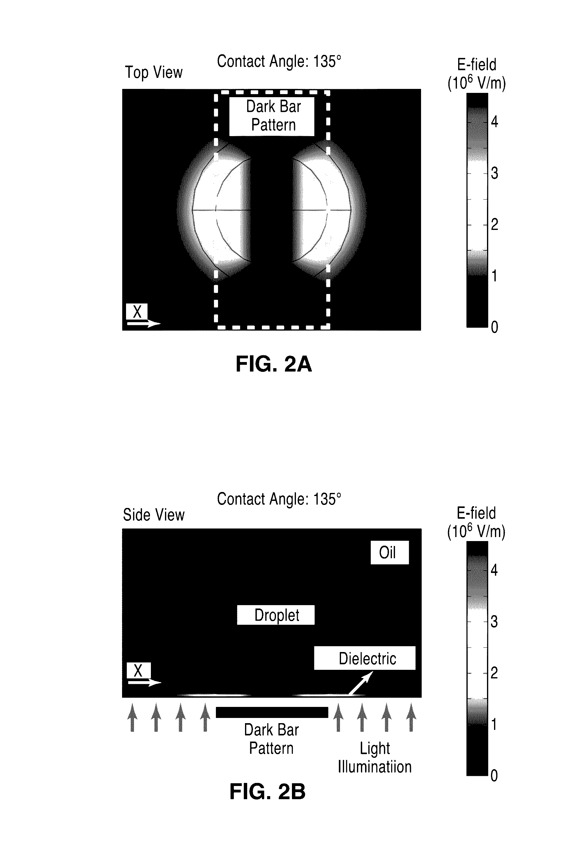
[0081]12. The apparatus of embodiment 1, wherein droplets within said first fluid are stretched and split in response to sudden illumination of a dark bar in said light pattern.

[0082]13. The apparatus of embodiment 1: wherein said droplets comprise droplets of...


PUM


Abstract

A single-sided continuous optoelectrowetting (SCOEW) device for manipulating droplets retained in a fluid over the SCOEW device with dynamic patterns of low intensity light, such as from a display screen, is described. A single pair of lateral electrodes are utilized for providing a lateral electric field bias, with transport motion controlled in response to projecting light through a photoconductive layer and dielectric layer adjacent to which droplets are retained. The device is configured for optically manipulating droplets having volumes spanning over five orders of magnitude, and can be configured to perform droplet dispensing, transport, splitting, merging, mixing and other droplet manipulation functions involving any of the above on a single sided surface.

Description

CROSS-REFERENCE TO RELATED APPLICATIONS[0001]This application claims priority from U.S. provisional patent application Ser. No. 61 / 370,009 filed on Aug. 2, 2010, incorporated herein by reference in its entirety.STATEMENT REGARDING FEDERALLY SPONSORED RESEARCH OR DEVELOPMENT[0002]This invention was made with Government support under Grant No. 0747950, awarded by the National Science Foundation. The Government certain rights in this invention.INCORPORATION-BY-REFERENCE OF MATERIAL SUBMITTED ON A COMPACT DISC[0003]Not ApplicableNOTICE OF MATERIAL SUBJECT TO COPYRIGHT PROTECTION[0004]A portion of the material in this patent document is subject to copyright protection under the copyright laws of the United States and of other countries. The owner of the copyright rights has no objection to the facsimile reproduction by anyone of the patent document or the patent disclosure, as it appears in the United States Patent and Trademark Office publicly available file or records, but otherwise re...

Claims


Application Information

Patent Timeline
IPC IPC(8): C25B7/00B01L3/00
CPCB01L3/502792B01L2300/0816B01L2400/0427
Inventor CHIOU, PEI-YUPARK, SUNG-YONG
Owner RGT UNIV OF CALIFORNIA
Learn More