
Methods and apparatus for signal flow graph pipelining that reduce storage of temporary variables

a signal flow graph and temporary variable technology, applied in the direction of instruments, digital computers, computing, etc., can solve the problems that the underlying processor architecture may present limitations affecting the efficiency of implementing functions

Inactive Publication Date: 2016-11-29
PECHANEK GERALD GEORGE
View PDF3 Cites 4 Cited by
  • Summary
  • Abstract
  • Description
  • Claims
  • Application Information

AI Technical Summary

Benefits of technology

The present invention provides improvements for executing signal flow graph expressions in processor architectures. These improvements include organizing processors and memory in stages according to dimensions, using multiple embodiments of the present invention to address various aspects of the processor architecture. The network of nodes in the signal flow graph is designed to have p planes of R×C arrays of Ar,c,p nodes and Rr,c,p nodes, with each plane containing a different p and r. The network also includes p planes of R×C arrays of Sr,c,p nodes and Rr,c,p nodes, with each plane containing a different r. The network is directly coupled to R×C arrays of Rr,c,p nodes and Rr,c,p nodes in a second dimension, and each node in the network is operable to select a data value from directly coupled nodes and output the selected data value. The method also includes decoding a chain of instructions and identifying an execution unit and operand input pipeline register for each instruction. Overall, the invention provides improved performance and efficiency for executing signal flow graph expressions in processor architectures.

Problems solved by technology

One of the problems associated with increasing performance in multiprocessor parallel processing systems is the efficient accessing of data or instructions from memory.
Having adequate memory bandwidth for sharing of data between processors is another problem associated with parallel processing systems.
These problems are related to the organization of the processors and memory modules and the processor architecture used for data communication between a processor, including execution units, and a plurality of memories and between processors.
However, the underlying processor architecture may present limitations that affect the efficiency of implementing functions described using Kronecker product expressions and other signal analysis techniques.

Method used


Image

  • Methods and apparatus for signal flow graph pipelining that reduce storage of temporary variables
  • Methods and apparatus for signal flow graph pipelining that reduce storage of temporary variables
  • Methods and apparatus for signal flow graph pipelining that reduce storage of temporary variables

Examples


Embodiment Construction

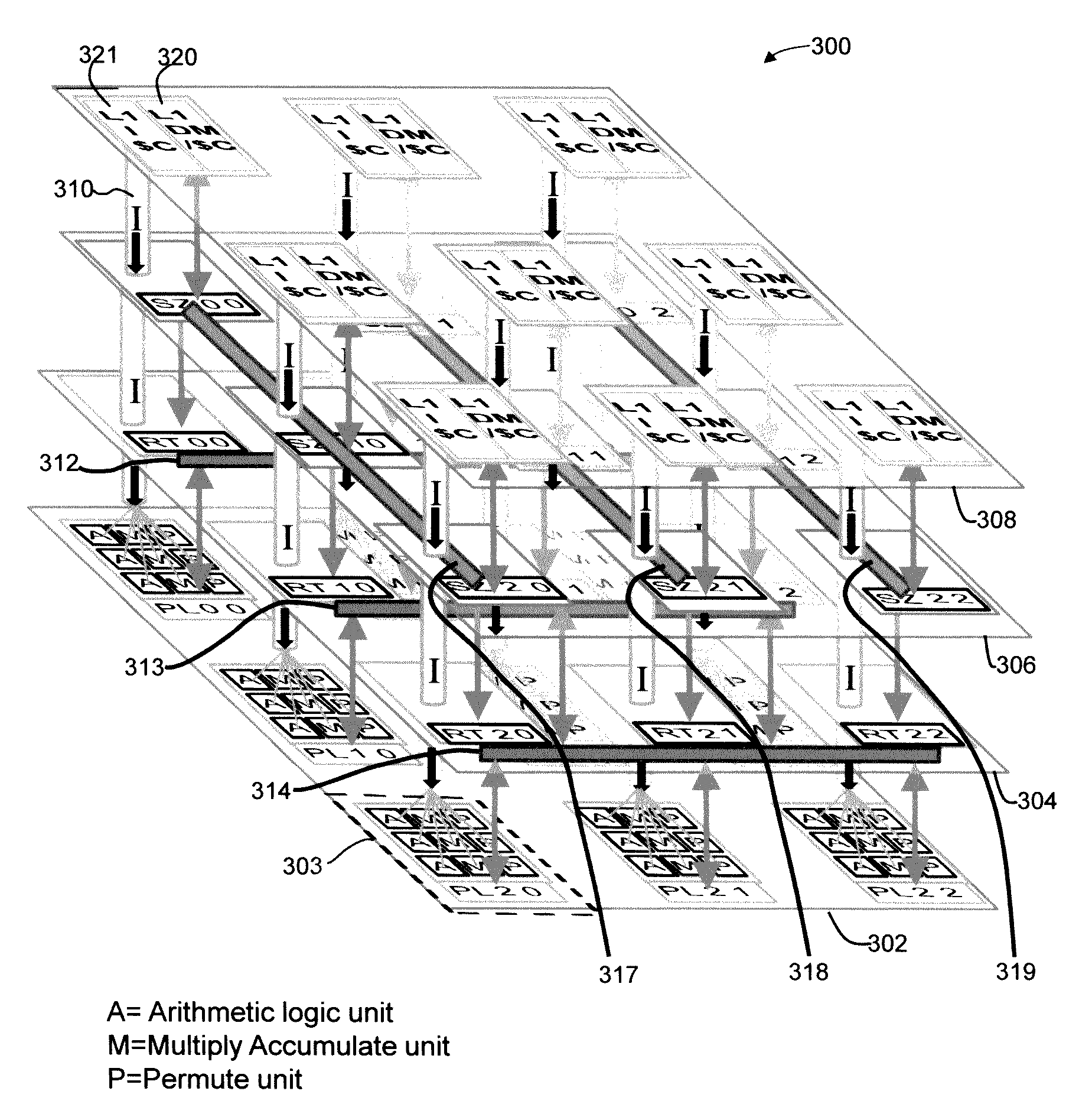
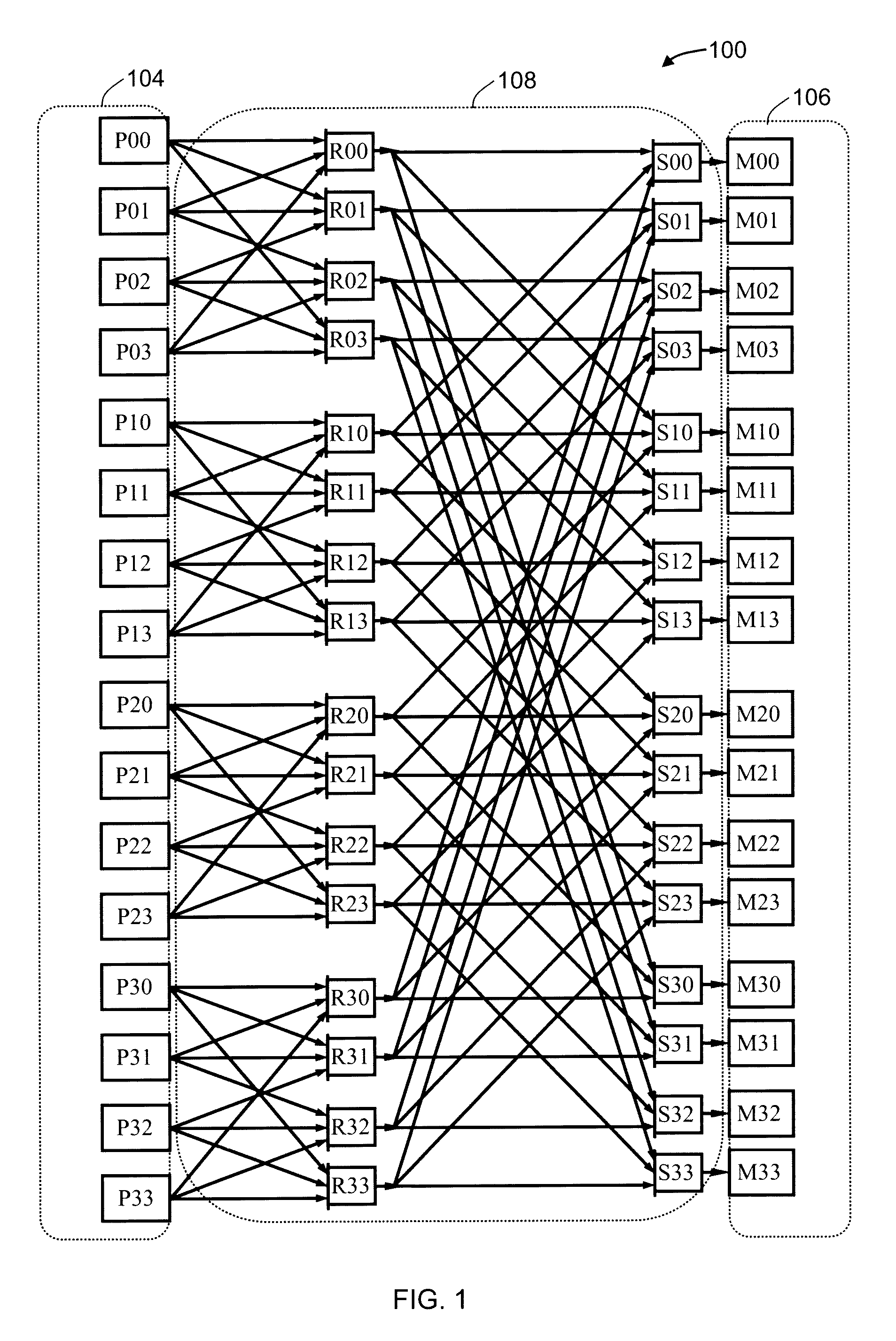
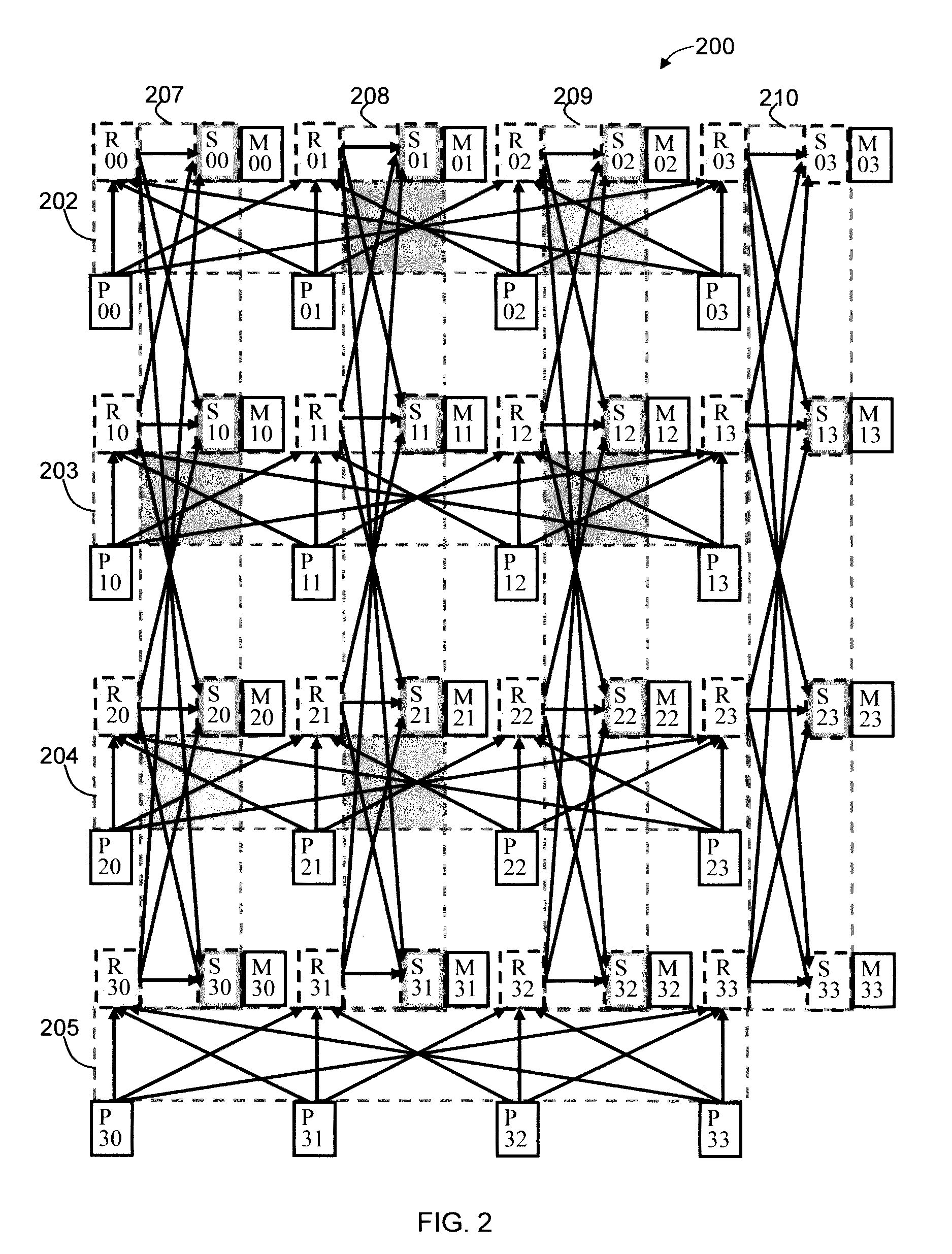
[0071]FIG. 1 illustrates a Wings array memory (WAM) sixteen processor network for store operations (WAM16S) 100 in accordance with an embodiment of the present invention. Processors 104 which comprise sixteen processors P00-P33 are illustrated as nodes that each can initiate a store operation to store data in a memory location in the memory blocks 106, consisting of sixteen memory blocks M00-M33, also referred to as memory nodes. The processor and memory block nodes are organized in linear arrays and identified according to a G×H matrix where, in this example, G equals four representing the number of rows in the matrix and H equals four representing the number of columns. A processor Pg,h, a memory block Mg,h, and internal nodes of the network are labeled in a row g by column h format where g ∈ {0, 1, . . . , G−1} and h ∈ {0, 1, . . . , H−1}. The processors are not directly connected to each other nor are the memory blocks directly connected to any of the other memory blocks. The pr...


PUM


Abstract

A system for pipelining signal flow graphs by a plurality of shared memory processors organized in a 3D physical arrangement with the memory overlaid on the processor nodes that reduces storage of temporary variables. A group function formed by two or more instructions to specify two or more parts of the group function. A first instruction specifies a first part and specifies control information for a second instruction adjacent to the first instruction or at a pre-specified location relative to the first instruction. The first instruction when executed transfers the control information to a pending register and produces a result which is transferred to an operand input associated with the second instruction. The second instruction specifies a second part of the group function and when executed transfers the control information from the pending register to a second execution unit to adjust the second execution unit's operation on the received operand.

Description

RELATED APPLICATION DATA[0001]The present application claims the benefit of U.S. Provisional Application No. 61 / 862,075 filed Aug. 4, 2013 and claims the benefit of U.S. Provisional Application No. 61 / 905,265 filed Nov. 17, 2013, which are incorporated by reference herein in their entirety.CROSS REFERENCE TO RELATED APPLICATIONS[0002]The U.S. Pat. Nos. 7,581,079, 7,886,128, 8,156,311, and 8,443,169 and U.S. patent application entitled “Interconnection Network Connecting Operation-Configurable Nodes According to One or More Levels of Adjacency in Multiple Dimensions of Communication in a Multi-Processor and a Neural processor” U.S. application Ser. No. 13 / 792,039 filed on Mar. 9, 2013 have the same inventor, are related patents and application, and are hereby incorporated by reference in their entirety.FIELD OF INVENTION[0003]The present invention relates to unique and improved methods and apparatuses for processor architecture and organizations of processors and memory modules such ...

Claims


Application Information

Patent Timeline
Patent Type & Authority Patents(United States)
IPC IPC(8): G06F9/38G06F15/173
CPCG06F9/3895G06F15/17387G06F9/30181G06F9/3828G06F9/3836G06F9/3888G06F9/3851G06F9/30043G06F9/3838
Inventor PECHANEK, GERALD GEORGE
Owner PECHANEK GERALD GEORGE
Learn More