Actuation of distributed load management devices on aerodynamic blades

a distributed load management and blade technology, applied in the direction of machines/engines, sustainable transportation, mechanical equipment, etc., can solve the problems of increasing the number of components, and increasing the number of situations, so as to reduce the duty cycle of load management devices and increase power

Active Publication Date: 2016-11-29
GE INFRASTRUCTURE TECH INT LLC
View PDF11 Cites 3 Cited by
  • Summary
  • Abstract
  • Description
  • Claims
  • Application Information

AI Technical Summary

Benefits of technology

[0011]One or more aspects of the invention overcomes the limitations in the prior art by providing actuation sequences to actuate one or more load management devices on an airfoil. For example, in some embodiments actuation sequences are provided for actuating less than all of a plurality of load management devices on a wind turbine and / or a wind turbine blade. The actuation sequences may be employed in response to sensed operating conditions, such that a desired result (e.g., reduced loads such as loads on the blades, tower, drive train, etc.; increased power; reduce duty cycles of load management devices; etc.) may be achieved.

Problems solved by technology

However, the choice of rotor attributes for a wind turbine, such as its diameter, is a design trade-off between longer blades for more energy production in low winds and shorter blades for load limitation in high winds.
But at high wind speeds, a wind turbine having longer blades places greater demands on the components and creates more situations where the turbine must be shut down to avoid damaging components.
Even in situations where the average wind speed is not high enough to cause damage, periodic wind gusts may change both the speed and direction of the wind and apply forces that may be strong enough to damage equipment.
However, pitch control can be fairly slow to respond to changes in the wind and is relatively ineffective to loads imparted by sudden wind gusts.
However, both types of stall control systems can be difficult to optimize and slow to respond, and may suffer from lower predictability of results than desired.
While variable length rotor blade systems have certain advantages, they may suffer drawbacks in erratic wind conditions or may be too slow to respond when experiencing a wind gust.
However, in such embodiments, some deflectors may be deployed more than others, leading to hyperactivity of some (and thus early failure) and under usage of others.
Further, depending on a spanwise location of each deployed air deflector, for certain conditions some deflectors may be less effective than others, leading to more than necessary deflectors being deployed (and thus ultimately increasing the duty cycle total for the system as a whole).

Method used


Image

  • Actuation of distributed load management devices on aerodynamic blades
  • Actuation of distributed load management devices on aerodynamic blades
  • Actuation of distributed load management devices on aerodynamic blades

Examples


Embodiment Construction

[0027]In the following description of the various embodiments, reference is made to the accompanying drawings, which form a part hereof, and in which is shown by way of illustration various embodiments in which the invention may be practiced. It is to be understood that other embodiments may be utilized and structural and functional modifications may be made without departing from the scope of the present invention.

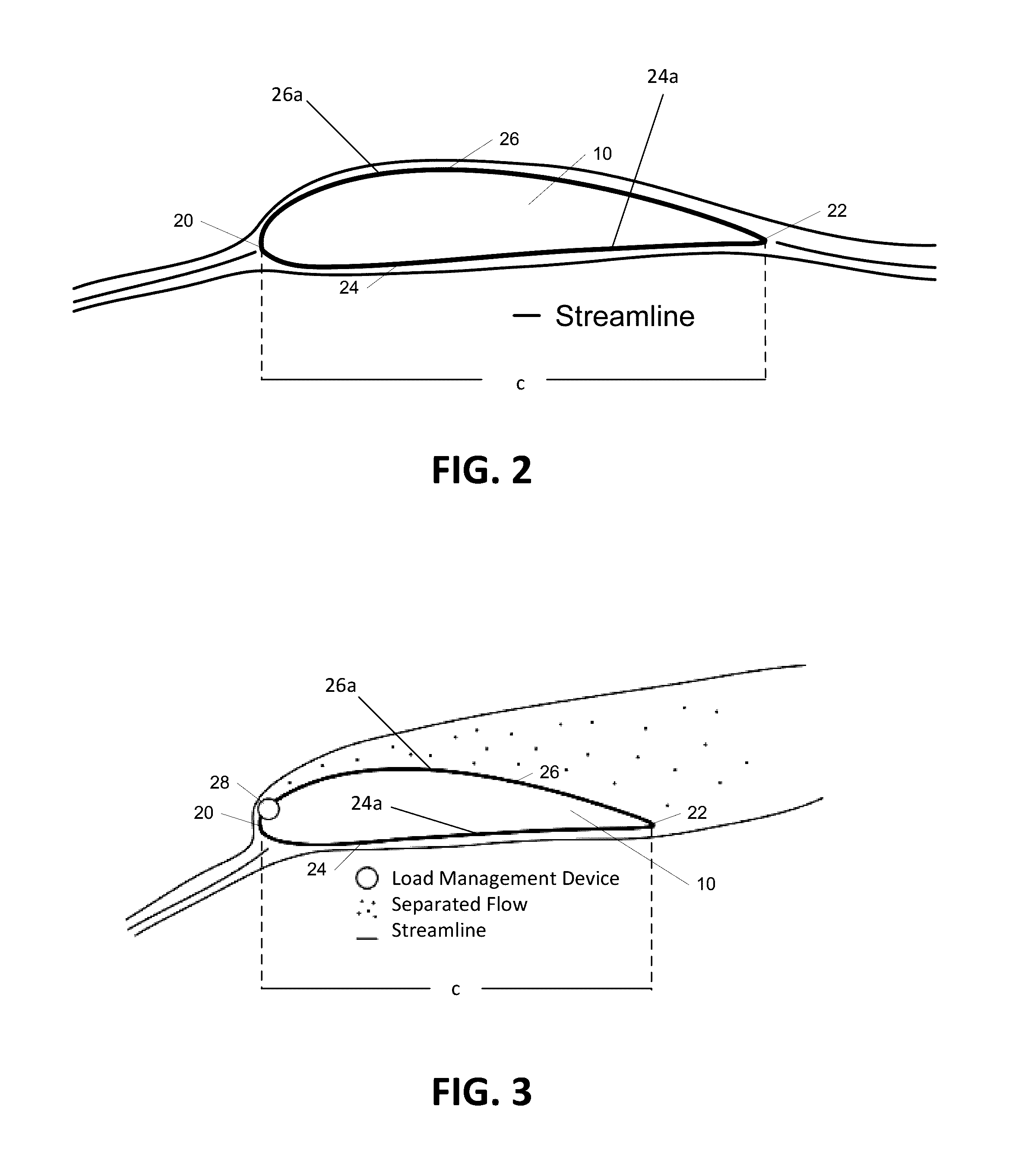
[0028]Aspects of the present invention are directed to multiple load management devices disposed on a wind turbine and methods of actuating one or more of the load management devices in response to sensed operating conditions. In addition, aspects of the invention are directed to actuating less than all of the load management devices on a wind turbine blade, and actuation sequences used in determining which load management devices to actuate.

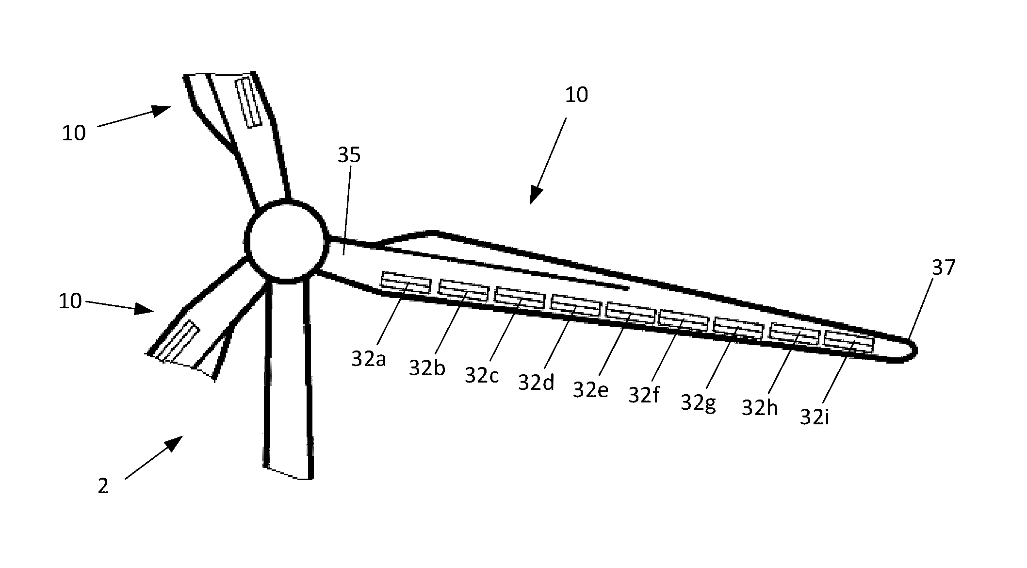
[0029]FIG. 1 shows a wind turbine 2 on a foundation 4 with a tower 6 supporting a nacelle 8. One or more blades 10 are attached to a...


PUM


Abstract

Systems, apparatuses, and methods are provided for actuating less than all of a plurality of load management devices on a wind turbine and / or a wind turbine blade. In some embodiments, the actuation sequences may be a root-to-tip, tip-to root, maximum-distributed-load, random, and / or a cycle-count actuation sequence. Further, a combination of two or more actuation sequences may be utilized to achieve a desired result. The system may choose an appropriate blade-based and / or rotor-based actuation sequence according to operating conditions, may alternate actuation sequences, and / or may employ different actuation sequences among the plurality of blades of a wind turbine. The load management devices may be actuated to different maximum heights and / or may be configured to be actuated to variable heights. The load management devices may be included as part of a distributed management system providing a corresponding controller and / or sensor at each load management device.

Description

TECHNICAL FIELD[0001]This application relates generally to the design and control of a wind turbine. More particularly, some aspects of the invention relate to modifying the aerodynamics of a wind turbine.BACKGROUND[0002]With their decreased availability and adverse impact to the environment, fossil fuels and other conventional energy sources are continually declining in popularity while clean, renewable energy source have seen rapid growth. In the coming years, as these fossil fuels continue to become scarce and as knowledge regarding the environmental impact of such energy sources becomes available, the demand for clean, renewable energy will continue to increase. One such source of clean, renewable energy is wind power. For example, kinetic energy from wind may be transmitted into electricity using, e.g., a wind turbine. Accordingly, electricity may be produced without burning any of these costly, environmentally hazardous fossil fuels.[0003]Wind turbines create power proportiona...

Claims


Application Information

Patent Timeline
Patent Type & Authority Patents(United States)
IPC IPC(8): F04D27/02F03D7/02
CPCF03D7/022F03D7/024F03D7/0232F05D2240/31Y02E10/721Y02E10/722Y02E10/723Y02E10/72Y02T50/60F05B2240/3052
Inventor BAKER, JONATHON PAULBUTTERWORTH, JEFFREY AUSTINKHAN, JEHAN ZEBLIN, GUOJIANMAYDA, EDWARD ANTHONYRICKARDS, ERICK JAMESWEHRHAN, TOBIAS GUENTHER
Owner GE INFRASTRUCTURE TECH INT LLC
Why Eureka
Try Eureka