
Distribution of return paths for improved impedance control and reduced crosstalk

Active Publication Date: 2016-11-22
ALTERA CORP
View PDF20 Cites 5 Cited by
  • Summary
  • Abstract
  • Description
  • Claims
  • Application Information

AI Technical Summary

Benefits of technology

The patent text describes a way to improve the connection between integrated circuit components by distributing signal, power, and ground connections evenly throughout the connection array. This helps to reduce signal integrity problems and ensure good return paths. By doing so, a strong ground reference network can be formed, which helps to reduce ground bounce, control impedance, and arrest the propagation of noise. As a result, signal integrity is sufficiently robust to support high-speed operations in the GHz region. Overall, this method improves the stability and reliability of the connection.

Problems solved by technology

In addition, since the number of connections itself does not guarantee good return paths, these ground connections are placed near the input / output signal connections to function effectively as a return path.

Method used


Image

  • Distribution of return paths for improved impedance control and reduced crosstalk
  • Distribution of return paths for improved impedance control and reduced crosstalk
  • Distribution of return paths for improved impedance control and reduced crosstalk

Examples


Embodiment Construction

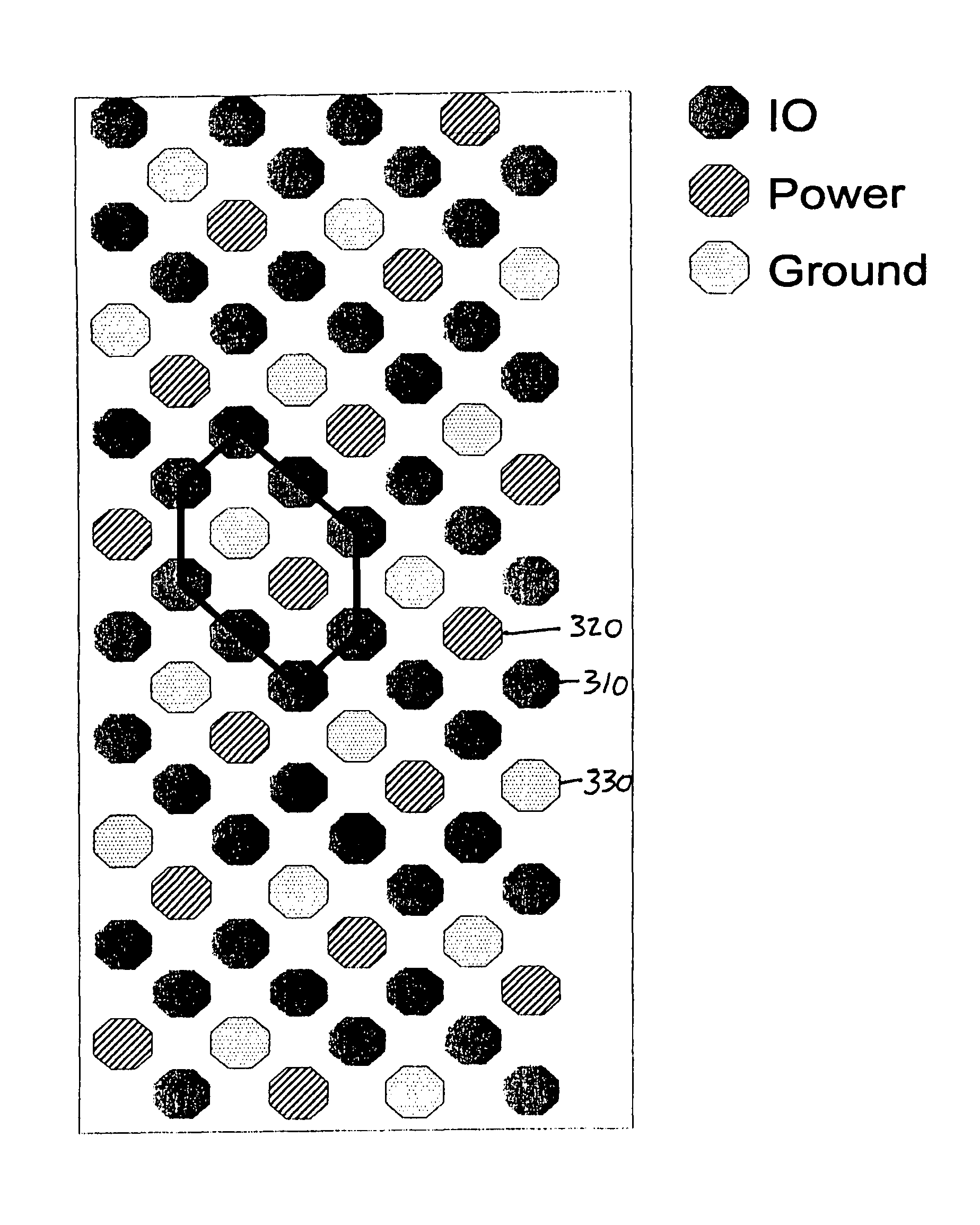
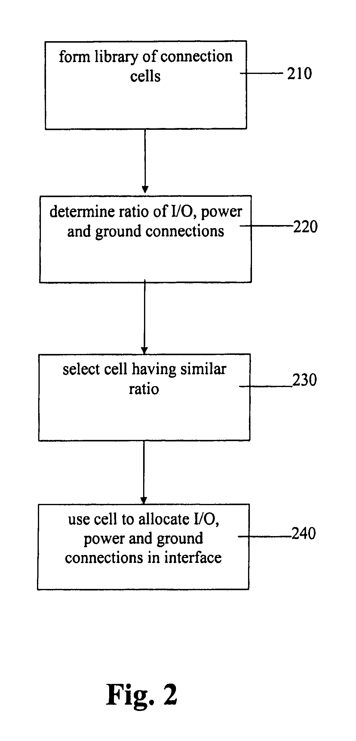
[0018]The interface between an integrated circuit die and substrate or between a substrate and higher level substrate or printed circuit board comprises input / output (I / O) signal, power and ground connections. Typically, these connections are made by solder balls or solder bumps and pads. In laying out these connections, the primary goal is to provide a close return path for every I / O signal. The secondary goal is to provide a uniform network to control impedance. These objectives can be achieved by following a set of rules in constructing the array of I / O signal, power and ground bumps. In particular, as shown in the flowchart of FIG. 2, at step 210 sets of connection cells are devised having different ratios of signal, power and ground connections in which the signal connections are all within a maximum distance of a power and / or a ground connection. In addition, the shapes of the cell must be such that the cells fit together in a repeatable array that fully covers the plane of th...


PUM


Abstract

To achieve an even distribution of different types of connections, sets of connection cells have been devised having different ratios of signal, power and ground connections in which the signal connections are all within a maximum distance of a power and / or a ground connection. In addition, the shapes of the cells are such that the cells fit together in a repeatable array that fully covers the plane of the interface, i.e., an array that tiles the plane. Accordingly, to distribute the connections substantially uniformly across the interface, the ratio of the number of signal connections, power connections and ground connections is determined; a cell is selected from the set of cells that has approximately the same ratio of the number of signal connections, power connections and ground connections; and the selected cell is repeatedly used to allocate the signal, power and ground connections in accordance with the distribution of connections in the selected cell until all the connections are distributed.

Description

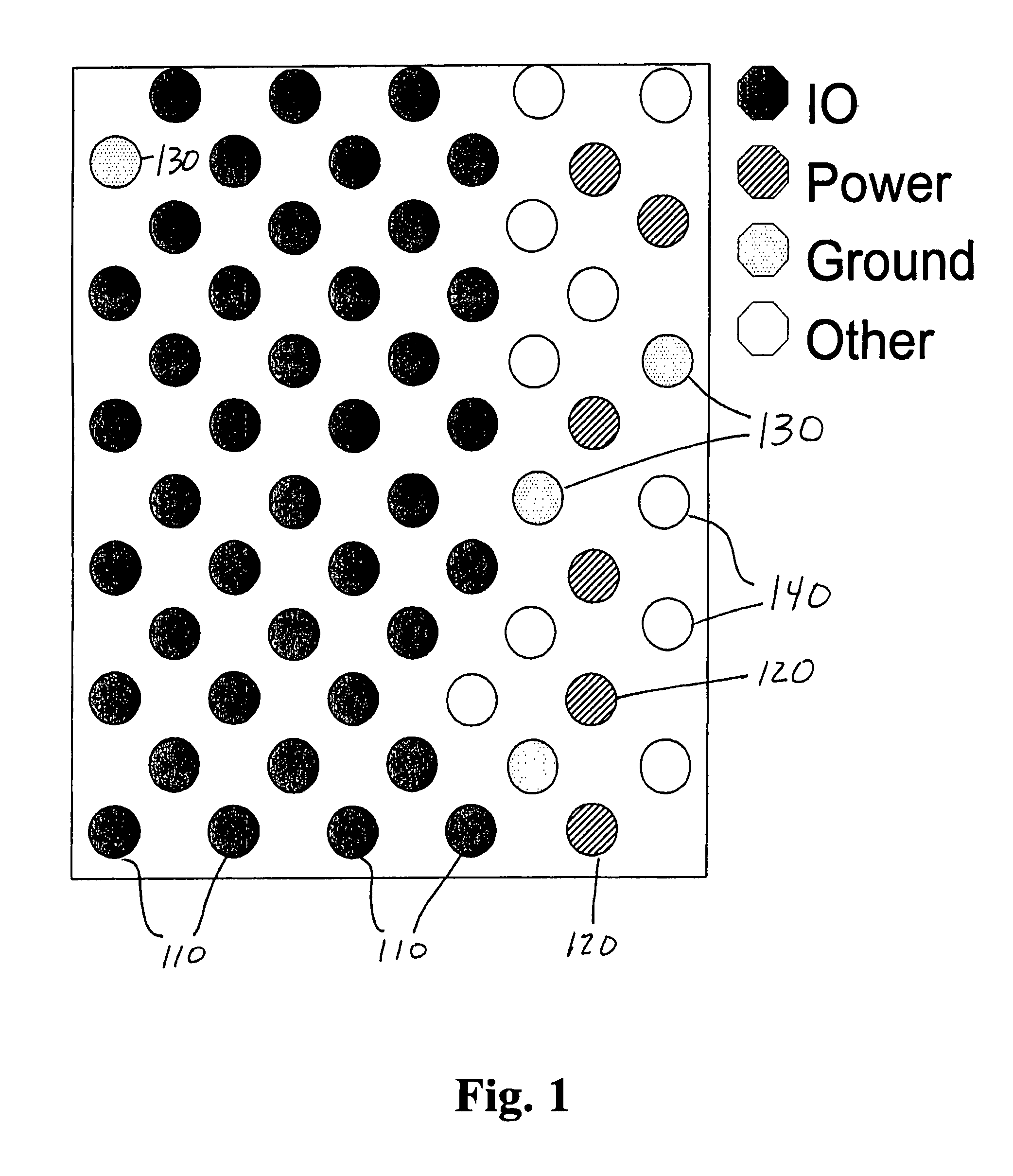
CLAIM OF PRIORITY[0001]This application claims the benefit of the Apr. 7, 2006, filing date of our provisional application No. 60 / 790,023, which is incorporated herein by reference.BACKGROUND OF THE INVENTION[0002]FIG. 1 depicts a typical rectilinear connection pattern at an electrical interface. Illustratively, the interface is the interface between an integrated circuit and the substrate on which it is mounted which is known as the controlled, chip collapse connection (C4) and the individual connectors are solder balls or solder bumps and the pads on which they are mounted. Alternatively, the interface could be between a substrate and a higher level substrate or printed circuit board. Typically, the connections between the die and the substrate include connections for input / output (I / O) signals 110, for power 120, for ground 130, and for other purposes 140. As shown in FIG. 1, typical connection patterns tend to segregate each type of connection from the other types so that substa...

Claims


Application Information

Patent Timeline
IPC IPC(8): H05K1/14H05K1/11H05K3/42
CPCH05K1/14H05K1/114H05K3/429H01L23/48H05K1/0296H05K1/111H05K2201/10674H01L23/49838H01L23/50H01L24/00H01L2224/13101H01L24/14H01L24/13Y02P70/50H01L2924/014H01L2924/00014
Inventor RANGAN, GOPINATHNGUYEN, KHAISUNG, CHIAKANG
Owner ALTERA CORP
Learn More