Eureka AIR delivers breakthrough ideas for toughest innovation challenges, trusted by R&D personnel around the world.

Wireless power for portable articles

a portable, wireless technology, applied in the direction of chairs, diagnostic recording/measuring, furniture parts, etc., can solve the problems of increasing the effort required to move electrical receptacles, partially exposed electrical contacts within the work area, etc., and achieve the effect of quick reconfiguration of furnishings and power connections

Active Publication Date: 2016-11-01
BYRNE NORMAN R
View PDF112 Cites 26 Cited by
  • Summary
  • Abstract
  • Description
  • Claims
  • Application Information

AI Technical Summary

Benefits of technology

[0011]Thus, the wireless power system of the present invention provides users of a work area with access to electrical power at different locations within the area, and allows the area to be reconfigured according to the desired types and locations of furniture, as well as the desired types and locations of electrical receptacles or outlets or wireless power connections, but without requiring cabling or wiring to extend through the work area, and without the need to establish direct contact electrical connections. This permits high and / or low voltage power to be provided throughout a work area, which can be used for powering or charging hand-held electronics, lighting, appliances, or the like, while facilitating the rapid reconfiguration of furnishings and power connections in the work area.

Problems solved by technology

However, electrical power receptacles that are located remotely from walls, floors, or ceilings typically require exposed cords or wiring that can create a trip hazard or limit access to certain areas of the work area, can become tangled, and can result in partially-exposed electrical contacts within the work area.
In addition, the typical need to establish direct electrical connections increases the effort required to move electrical receptacles, and is limited by the length of wiring that is readily available, as well as the routing paths available for such wiring.

Method used


Image

  • Wireless power for portable articles
  • Wireless power for portable articles
  • Wireless power for portable articles

Examples


Embodiment Construction

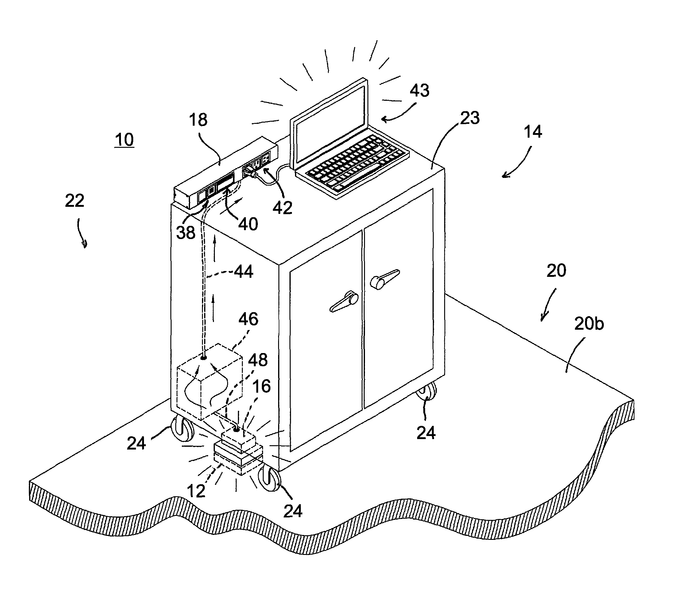
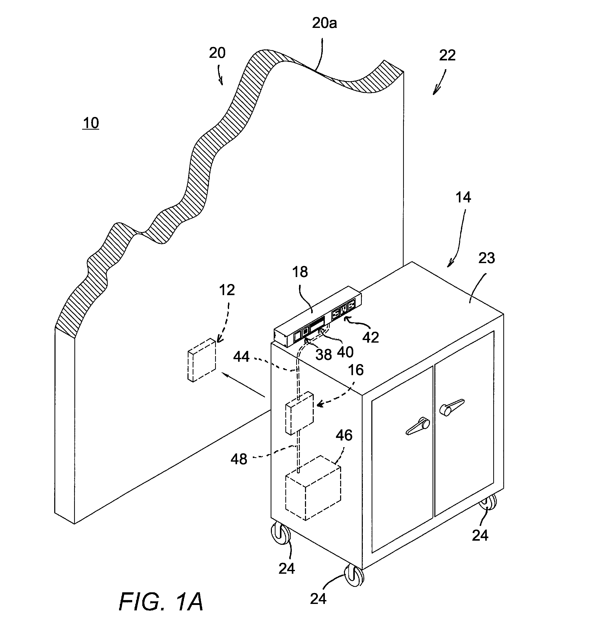
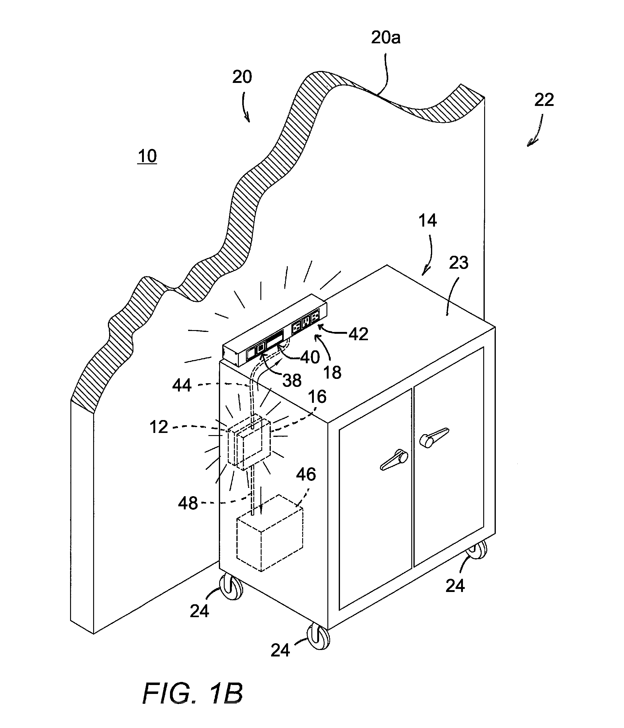
[0040]A wireless power system facilitates the placement and relocation of electrical receptacles and / or devices within a work area, while reducing or eliminating the need for exposed electrical cords and simplifying the procedure for relocating the electrical devices or articles that contain electrical receptacles or outlets or access points. Referring now to the drawings and the illustrative embodiments depicted therein, a wireless electrical power system 10 includes a wireless electrical power transmitter 12, a portable article 14 such as an article of furniture or an electrical device, a wireless electrical power receiver 16, and an electrical power receptacle or outlet unit 18 at the portable article 14 (FIGS. 1A and 1B). The wireless electrical power transmitter 12 is typically mounted in a surface 20 that defines a portion of a work area 22. Examples of different types of surfaces 20 that may incorporate power transmitters 12 include a wall surface 20a (FIGS. 1A, 1B, 3A, 3B, a...


PUM

PropertyMeasurementUnit
voltageaaaaaaaaaa
transmission distanceaaaaaaaaaa
electrical poweraaaaaaaaaa

Abstract

A wireless electrical power system provides access to high voltage and / or low voltage electrical power at portable articles that are positionable at different locations within a work area, and substantially without the use of exposed cabling. The power system includes a portable article that is positionable at two or more locations within a work area. The work area is defined by a plurality of surfaces, at least one of which incorporates a wireless electrical power transmitter. The portable article incorporates a wireless electrical power receiver that is configured to receive electrical power from the wireless power transmitter when the wireless power receiver is sufficiently close to the wireless power transmitter. The portable article further includes an electrical power outlet that provides users in the work area with access to the electrical power.

Description

CROSS REFERENCE TO RELATED APPLICATION[0001]The present application claims the benefit of U.S. provisional application Ser. No. 61 / 884,171, filed Sep. 30, 2013, which is hereby incorporated herein by reference in its entirety.FIELD OF THE INVENTION[0002]The present invention relates to electrical power systems for providing users with access to electrical power within a work area.BACKGROUND OF THE INVENTION[0003]Electrical power receptacles or outlets are commonly located in work areas, such as at or near work surfaces, in walls, in floors, and in ceilings. However, electrical power receptacles that are located remotely from walls, floors, or ceilings typically require exposed cords or wiring that can create a trip hazard or limit access to certain areas of the work area, can become tangled, and can result in partially-exposed electrical contacts within the work area. In addition, the typical need to establish direct electrical connections increases the effort required to move elect...

Claims


Application Information

Patent Timeline
Patent Type & Authority Patents(United States)
IPC IPC(8): H01F37/00H02J5/00A47C7/72H02J7/02A47B13/00
CPCH02J5/005A47C7/725A47B13/00H02J7/025A61B5/6891H02J50/10H02J7/0042H02J50/40H02J2310/23H02J50/90
Inventor BYRNE, NORMAN R.KNAPP, ROBERT L.WARWICK, TIMOTHY J.BURDI, ROGER D.
Owner BYRNE NORMAN R
Why Eureka
Eureka Blog
Learn More