
Illumination system and projection apparatus

a projection apparatus and illumination system technology, applied in the field of optical system and display apparatus, can solve the problems of ineffective connection and transmission of light beams provided by light sources to light valves, inability to choose light sources with desirable optical performance, and inability to effectively connect and transmit light beams provided by light sources. to achieve good light output efficiency

Active Publication Date: 2016-11-01
CORETRONIC
View PDF16 Cites 18 Cited by
  • Summary
  • Abstract
  • Description
  • Claims
  • Application Information

AI Technical Summary

Benefits of technology

[0010]The invention provides an illumination system, having a good light output efficiency.
[0011]The invention provides a projection apparatus, having a good light output efficiency.
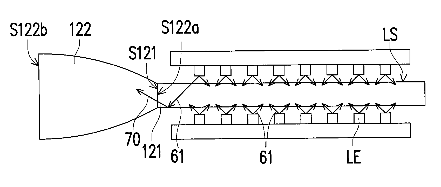
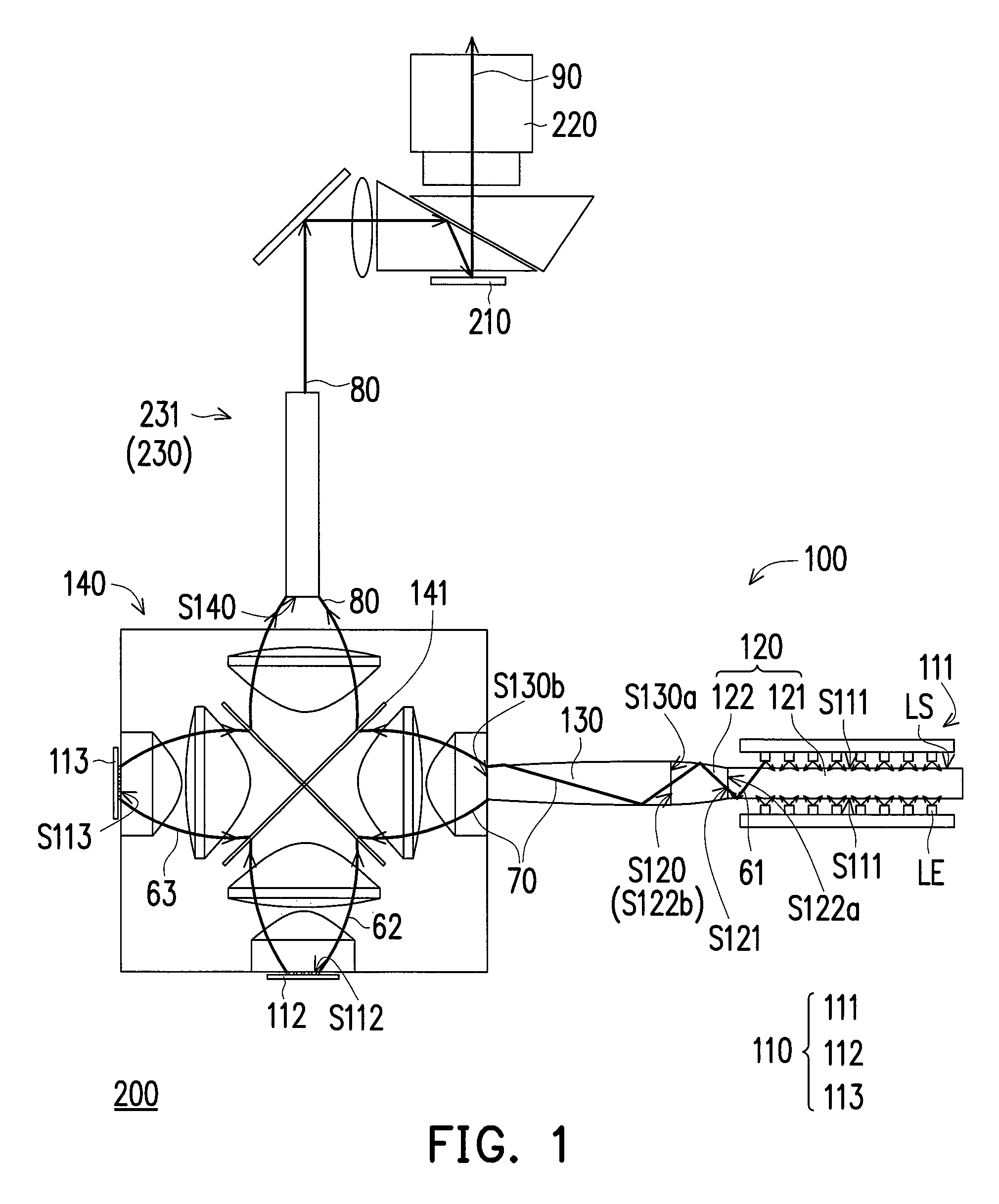
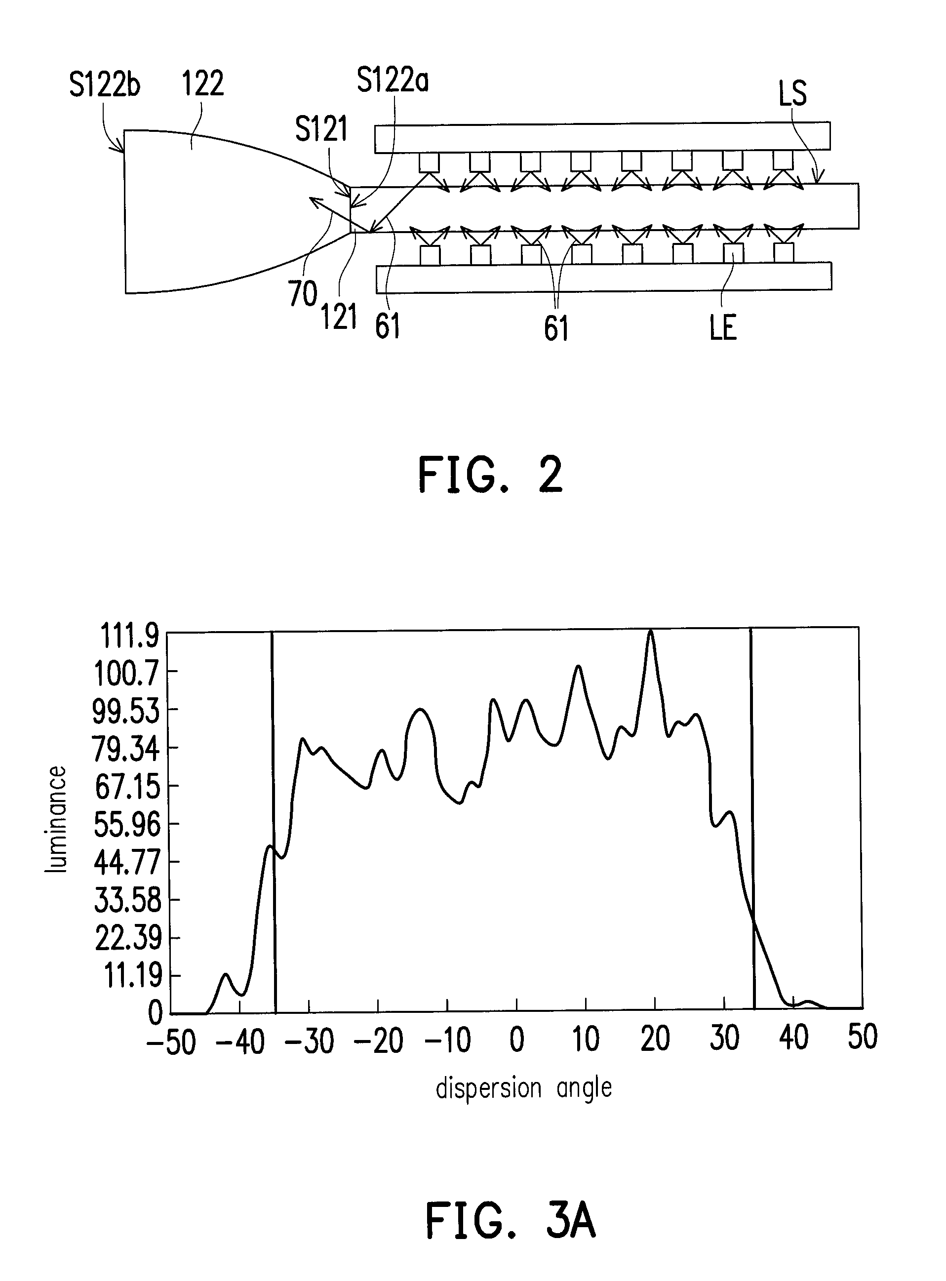
[0025]Based on the above, the embodiments at least have one of the following functions or effects. Since the projection apparatus and the illumination system according to the embodiments of the invention make use of the design that the area of the fifth illuminating surface of the light consolidating unit, the area of the fourth illuminating surface of the taper tunnel, and the area of each third illuminating surface correspond to each other, the light beams provided by the light sources are able to be collected effectively and transmitted to the light valve. Furthermore, the illumination system is capable of matching and adjusting the area of the fifth illuminating surface of the light consolidating unit, the area of the fourth illuminating surface of the taper tunnel, and the area of each third illuminating surface according to the E'tendue of the light valve, so as to improve the color temperature balance and light output efficiency of the red, green and blue light beams output by the illumination system. In addition, with the structural design of the light concentrating unit, the maximum light dispersion angle and uniformity of the first color light may also be appropriately adjusted to help design subsequent light coupling of the illumination system.

Problems solved by technology

However, under such circumstance, the choice on light sources is very limited, and it is unable to choose a light source having a desirable optical performance but having a different illuminating area and dispersion angle.
Besides, if the light source having a desirable optical performance but having different illuminating area and dispersion angle is chosen as a different light source in the illumination system, the light beam provided by the light source is unable to be effectively connected and transmitted to the light valve due to the difference in E'tendue.

Method used


Image

  • Illumination system and projection apparatus
  • Illumination system and projection apparatus
  • Illumination system and projection apparatus

Examples


Embodiment Construction

[0036]In the following detailed description of the preferred embodiments, reference is made to the accompanying drawings which form a part hereof, and in which are shown by way of illustration specific embodiments in which the invention may be practiced. In this regard, directional terminology, such as “top,”“bottom,”“front,”“back,” etc., is used with reference to the orientation of the Figure(s) being described. The components of the present invention can be positioned in a number of different orientations. As such, the directional terminology is used for purposes of illustration and is in no way limiting. On the other hand, the drawings are only schematic and the sizes of components may be exaggerated for clarity. It is to be understood that other embodiments may be utilized and structural changes may be made without departing from the scope of the present invention. Also, it is to be understood that the phraseology and terminology used herein are for the purpose of description an...


PUM


Abstract

An illumination system including a plurality of light source units, at least one light concentrating unit, at least one taper tunnel and a light consolidating unit is provided. The light concentrating unit corresponds to and is disposed beside one of the light source units. The light concentrating unit has a first illuminating surface, the light source unit corresponding to the light concentrating unit has a second illuminating surface, and the other light source units not corresponding to the concentrator have a third illuminating surface, respectively. The concentrator is disposed between the taper tunnel and the light source unit, and the taper tunnel has a fourth illuminating surface. The light consolidating unit has a fifth illuminating surface. The area of the fourth illuminating surface, and each of the third illuminating surfaces corresponds to each other. A projection apparatus is also provided.

Description

CROSS-REFERENCE TO RELATED APPLICATION[0001]This application claims the priority benefit of Taiwan application serial no. 103140968, filed on Nov. 26, 2014. The entirety of the above-mentioned patent application is hereby incorporated by reference herein and made a part of this specification.BACKGROUND OF THE INVENTION[0002]1. Field of the Invention[0003]The invention relates to an optical system and a display apparatus, and particularly relates to an illumination system and a projection apparatus.[0004]2. Description of Related Art[0005]With the progress of modern video technology, optical projection apparatuses have been widely used in the occasions of home theater, small conference report, and discussion. An optical projection apparatus includes an illumination system, a light valve, and a projection lens. The light source is configured to provide an illumination beam, the light valve is configured to convert the illumination beam into an image beam, and the projection lens is co...

Claims


Application Information

Patent Timeline
Patent Type & Authority Patents(United States)
IPC IPC(8): G03B21/28G03B21/00F21V8/00G03B21/20G03B21/14H04N9/31
CPCG03B21/204G02B6/0001G03B21/005G03B21/208G03B21/2013G03B21/2033G03B21/2066H04N9/3108H04N9/3111G02B6/0068
Inventor CHENG, CHUAN-TE
Owner CORETRONIC
Learn More