Eureka AIR delivers breakthrough ideas for toughest innovation challenges, trusted by R&D personnel around the world.

Dual-band multiple beam reflector antenna for broadband satellites

a technology of multiple beams and reflectors, applied in the direction of antennas, simultaneous aerial operations, electrical equipment, etc., can solve the problems of poor cross-over level between the beams generated by adjacent feeds (10 db), very limited space for other missions, and configuration restrictions. , to achieve the effect of high rf performan

Inactive Publication Date: 2016-10-25
EUROPEAN SPACE AGENCY
View PDF8 Cites 3 Cited by
  • Summary
  • Abstract
  • Description
  • Claims
  • Application Information

AI Technical Summary

Benefits of technology

The present invention provides a broadband communication satellite antenna that has a full dual-band multiple beam coverage. It uses a single main reflector that meets the size requirement for a satellite entering the fairing of current launch vehicles while maintaining high RF performance. The tilt angle of the main reflector is set to avoid blockage effects and ensure low cross polarization. The technical effect is to enable efficient and high-performing communication over a wide range of frequencies.

Problems solved by technology

A conventional reflector antenna configuration wherein feeds are designed to provide proper illumination of the main reflector typically results in poor cross-over level between the beams generated by adjacent feeds (10 dB or more).
Such a configuration is obviously very restrictive in terms of accommodation within the fairing of the launch vehicle due to the high number of apertures required.
Besides, as current beam sizes are in the range of 0.4 to 0.7 degree at Ka-band, reflector apertures in the range of two meters and more are required, which results in a satellite accommodation with two reflector antennas per lateral face and leaves very limited space for other missions.
However, due to the bandwidth limitations of the BFN, the full coverage needs to be produced with two separate apertures, one aperture for the transmit (Tx) coverage and one aperture for the receive (Rx) coverage.
A first category of solutions as described in the U.S. Pat. No. 7,522,116 B2 uses an over-sized reflector configuration, which may still lead to accommodation issues, or requires the use of advanced and complex reflector technology, e.g. deployable mesh reflectors, for smaller spot beam sizes.
Such satellite antenna leads to very high spill-over losses in the range of 3 to 10 dB, which significantly affects the antenna gain and overall system performance.
These high spill-over losses are related to a poor illumination of the reflector which also produces higher side lobe levels, and as a consequence degraded C / I performance.

Method used


Image

  • Dual-band multiple beam reflector antenna for broadband satellites
  • Dual-band multiple beam reflector antenna for broadband satellites
  • Dual-band multiple beam reflector antenna for broadband satellites

Examples


first embodiment

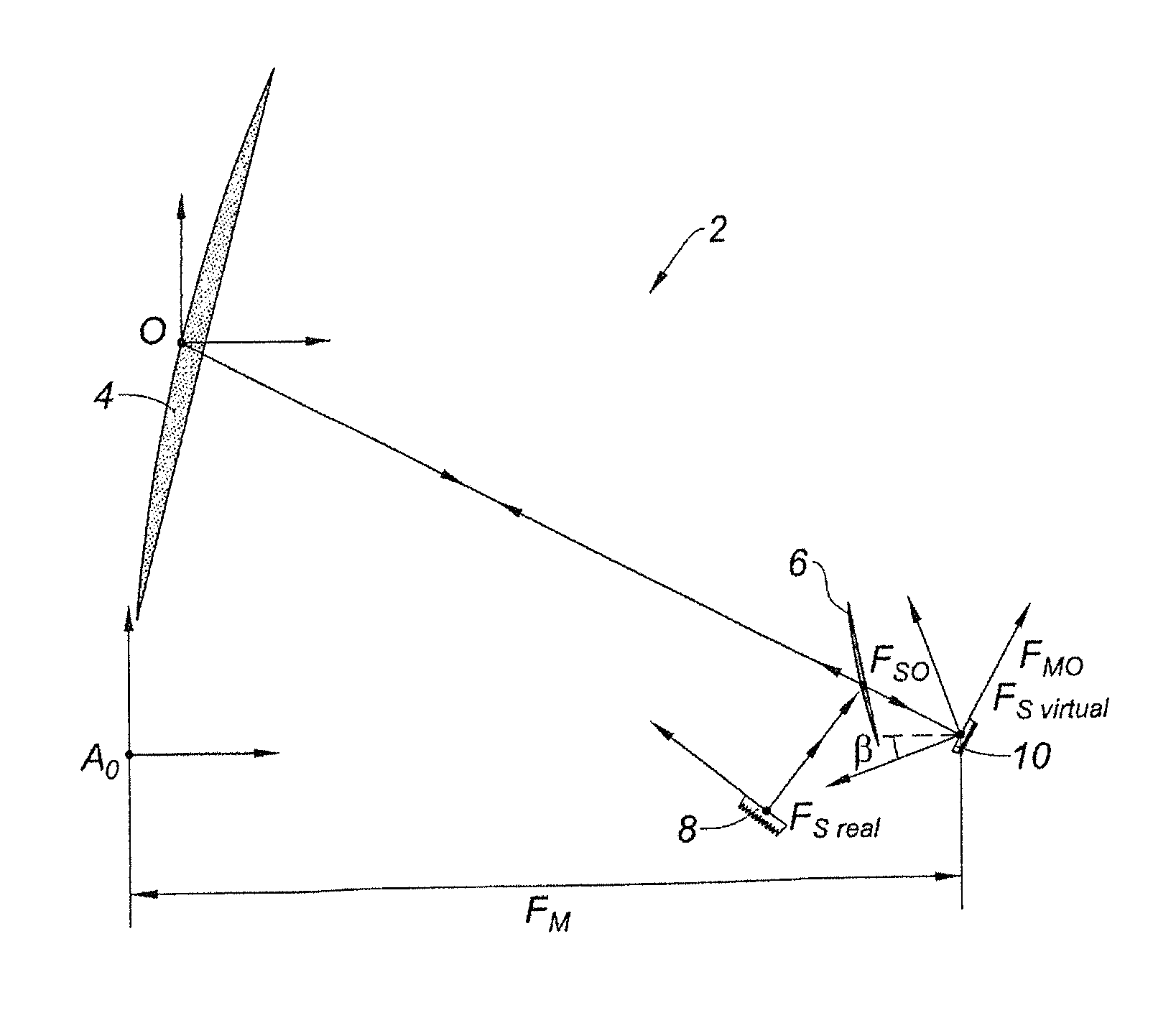
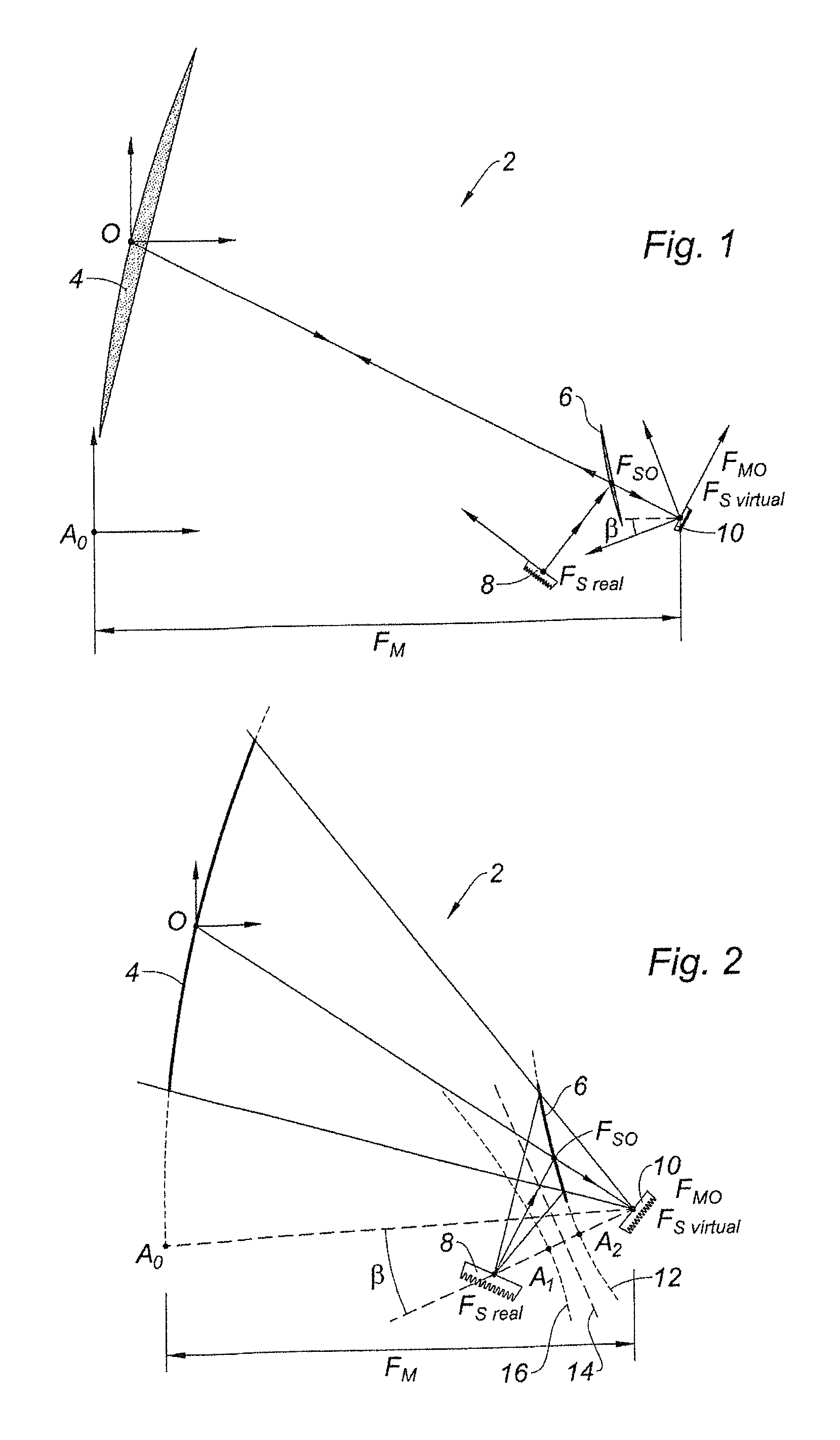
[0052]According to FIGS. 1-2 and the invention, a broadband communication satellite antenna 2, for producing a dual-band multiple beam coverage, made of a transmit multiple beam coverage operating in a first transmitting frequency band BTx and of a receive multiple beam coverage operating in a second receiving frequency band BR, is based on an offset dual-optics configuration.

[0053]The first transmitting frequency band BTx and the second receiving frequency band BRx are separate or in other terms do not overlap. These bands are two separate sub-bands of a same third band, here the Ka-band.

[0054]Generally in communication satellite applications, the third band is comprised within the family of L-band, S-band, C-band, X-band, Ku-band, Ka-band and Q / V-band.

[0055]The broadband communication satellite antenna 2 comprises a single main parabolic reflector 4, a hyperbolic sub-reflector 6, a first transmitting Multiple-Feed-per-Beam (MFB) feed system 8 configured to generate the first trans...

second embodiment

[0106]According to the FIGS. 10 and 11, and the invention, a broadband communication satellite antenna 202, for producing a dual-band multiple beam coverage, made of a transmit multiple beam coverage operating in a first transmitting frequency band BTx and of a receive multiple beam coverage operating in a second receiving frequency band BRx, is based on an offset dual-optics configuration.

[0107]Like the antenna 2 of FIGS. 1 and 2, the first transmitting frequency band BTx and the second receiving frequency band BRx are separate or in other terms do not overlap. These bands are two separate sub-bands of a same third band, here the Ka-band. As a variant, the third band may be also L-band, S-band, C-band, X-band, Ku-band or Q / V band.

[0108]The broadband communication satellite antenna 202 comprises a single main parabolic reflector 204, a hyperbolic sub-reflector 206, a first transmitting Multiple-Feed-per-Beam (MFB) feed system 208 configured to generate the first transmit coverage an...

third embodiment

[0124]According to the FIG. 12 and the invention, a broadband communication satellite antenna 302, for producing a dual-band multiple beam coverage, made of a transmit multiple beam coverage operating in a first transmitting frequency band BTx and of a receive multiple beam coverage operating in a second receiving frequency band BRx, is based on an offset dual-optics configuration.

[0125]Like the antennas 2 and 202, the first transmitting frequency band BTx and the second receiving frequency band BRx are separate or in other terms do not overlap. These bands are two separate sub-bands of a same third band, here the Ka-band. As a variant, the third band may be also L-band, S-band, C-band, X-band, Ku-band or Q / V-band.

[0126]The broadband communication satellite antenna 302 comprises a single main parabolic reflector 304, a flat sub-reflector 306, a first transmitting Multiple-Feed-per-Beam (MFB) feed system 308 configured to generate the first transmitting coverage and to illuminate the...


PUM


Abstract

A broadband satellite antenna for producing a dual-band multiple beam coverage in transmission and reception based on an offset dual-optics configuration that includes a single main parabolic reflector, a hyperbolic sub-reflector, a first transmitting Multiple-Feed-per-Beam feed system, and a second receiving Multiple-Feed-per-Beam feed system. The sub-reflector surface is a Frequency Selective Surface configured to transmit any electromagnetic signals in the higher frequency band and to reflect any electromagnetic signals in the lower frequency band. The Multiple-Feed-per-Beam feed systems are located at the main focal point FMO and at the first sub-reflector real focal point FSreal. The eccentricity e of the hyperbolic sub-reflector depends on a ratio between a preset lower frequency fL in the lower frequency band BL and a preset higher frequency fH in the higher frequency band BH. The first transmitting Multiple-Feed-per-Beam feed system and the second receiving Multiple-Feed-per-Beam feed system are geometrical scaled versions of each other.

Description

FIELD OF THE INVENTION[0001]The invention relates to a dual-band multiple beam reflector antenna for broadband communication satellites configured to provide a dual-band multiple beam coverage made of a transmit multiple beam coverage within a first transmitting frequency band (Tx) and a receive multiple beam coverage within a second receiving frequency band (Rx).BACKGROUND[0002]The current trend in satellite communications is to implement multiple beam coverage of congruent narrow spot beams, as it is already the case at Ka-band for current broadband applications. Investigations are on-going to extend the concept to other frequency bands and applications, such as C- and Ku-band.[0003]Multiple beam coverage is known to provide better antenna gain for a given antenna aperture size and significantly increases the communication satellite-based system capacity by frequency spectrum re-use on non-adjacent spot beams. Frequency re-use schemes implemented in satellite-based communication s...

Claims


Application Information

Patent Timeline
Patent Type & Authority Patents(United States)
IPC IPC(8): H01Q5/30H01Q19/19H01Q5/20
CPCH01Q5/30H01Q5/20H01Q19/19H01Q19/192H01Q3/2658H01Q15/0033H01Q15/16H01Q19/026H01Q19/028H01Q15/0046H01Q5/45
Inventor FONSECA, NELSON JORGE GONCALVES
Owner EUROPEAN SPACE AGENCY
Why Eureka
Eureka Blog
Learn More