
Printing system and method of printing a multilayer structure using radiation curable ink

a printing system and multi-layer structure technology, applied in the field of printing systems, can solve the problems of deformation, detachment of printed structures, and special mechanical stress, and achieve the effects of minimizing expansion/shrinkage mechanical stress, and improving thermal expansion coefficient differences

Active Publication Date: 2016-10-18
OCE TECH
View PDF11 Cites 2 Cited by
  • Summary
  • Abstract
  • Description
  • Claims
  • Application Information

AI Technical Summary

Benefits of technology

The patent text describes a method for printing a multi-layer structure using different inks that expand or shrink during the curing process. The amount of each ink is determined based on their expansion / shrinkage properties. This allows for better control of the composition of the layers and reduces mechanical stress between the layers and the receiving material. Furthermore, the inks are chosen so that their expansion and shrinkage properties cancel out, resulting in a negligible expansion / shrinkage property of the overall structure. This helps to minimize thermal stress between the layers and the receiving material. Overall, this method provides greater control over the mechanical properties of the printed structure.

Problems solved by technology

A problem of mechanical stress may be particularly pronounced in thick structures having e.g. a height of 0.5 to 10 mm.
This may cause a detachment of the printed structure or, in case of a thin and / or flexible receiving material, a deformation may occur.
Furthermore, mechanical stress between the printed structure and the receiving material may be caused by a thermal expansion coefficient difference between the ink and the receiving material.
The mechanical stress accumulates along the lateral extension of the printed structure, so that the problem is particularly pronounced when printed structures have a large extension in one or two directions on the surface of the receiving material.

Method used


Image

  • Printing system and method of printing a multilayer structure using radiation curable ink
  • Printing system and method of printing a multilayer structure using radiation curable ink
  • Printing system and method of printing a multilayer structure using radiation curable ink

Examples


first example

[0051]In a first example, a structure having a target thickness D of 0.2 mm is printed on a receiving material 20 in the form of thin polyester film having a thickness of 0.1 mm (Océ polyester MC500).

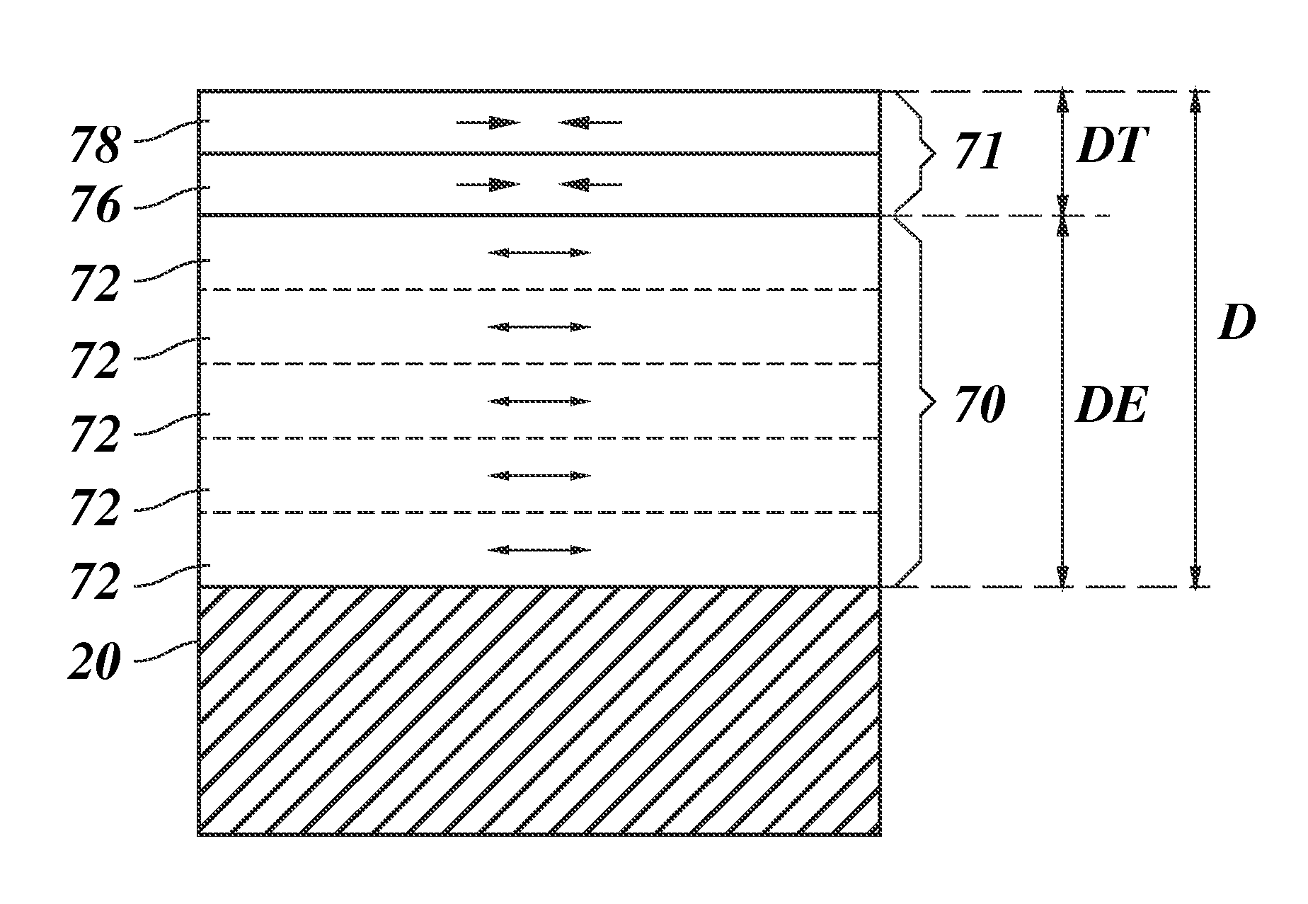
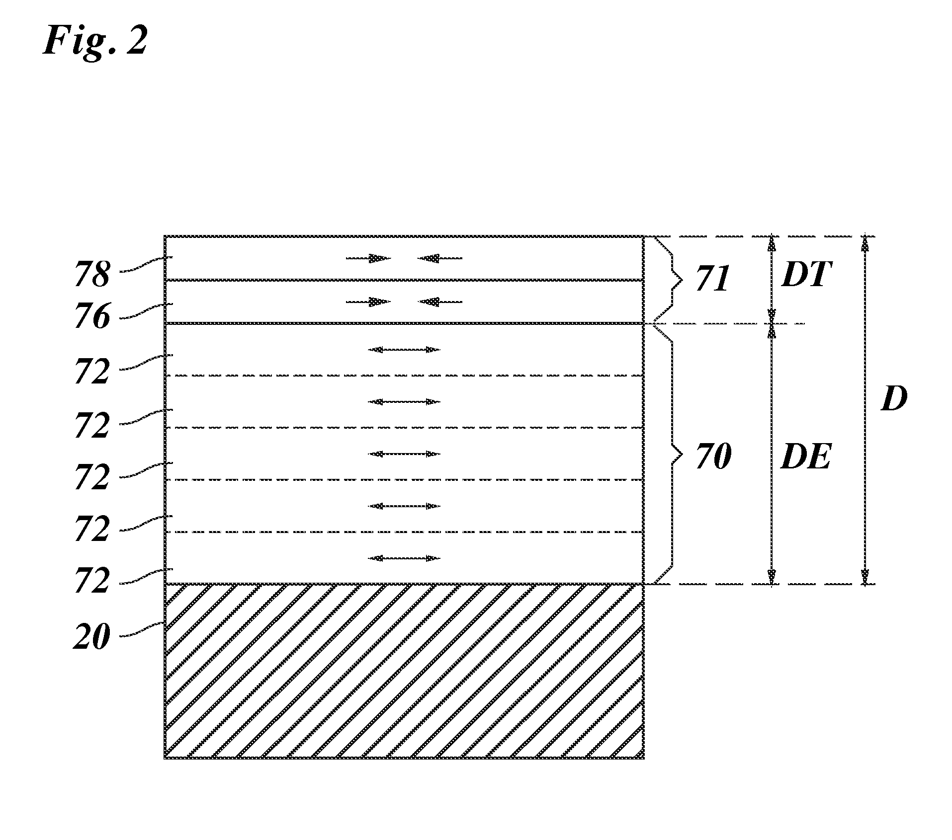
[0052]The structure comprises an elevation layer 70 and a top layer 71. The elevation layer 70 comprises one or more sub-layers 72, which are schematically shown in FIG. 2. The top layer 71 comprises a white cover layer 76, which completely covers the top surface of the elevation layer 70, and an image layer 78 reproducing image data P. A thickness DT of the top layer 71 is determined by the average thickness of the image layer 78 and the e.g. constant thickness of the optional white cover layer 76.

[0053]The white cover layer 76 is printed using the first ink 37 (W). The image layer 78 is printed using the first inks 35 (C, M, Y) in accordance with the image information P. The inks 35, 37 (C, M, Y, W) used for the top layer 71 have substantially the same curing expansion / shrinkage prope...

second example

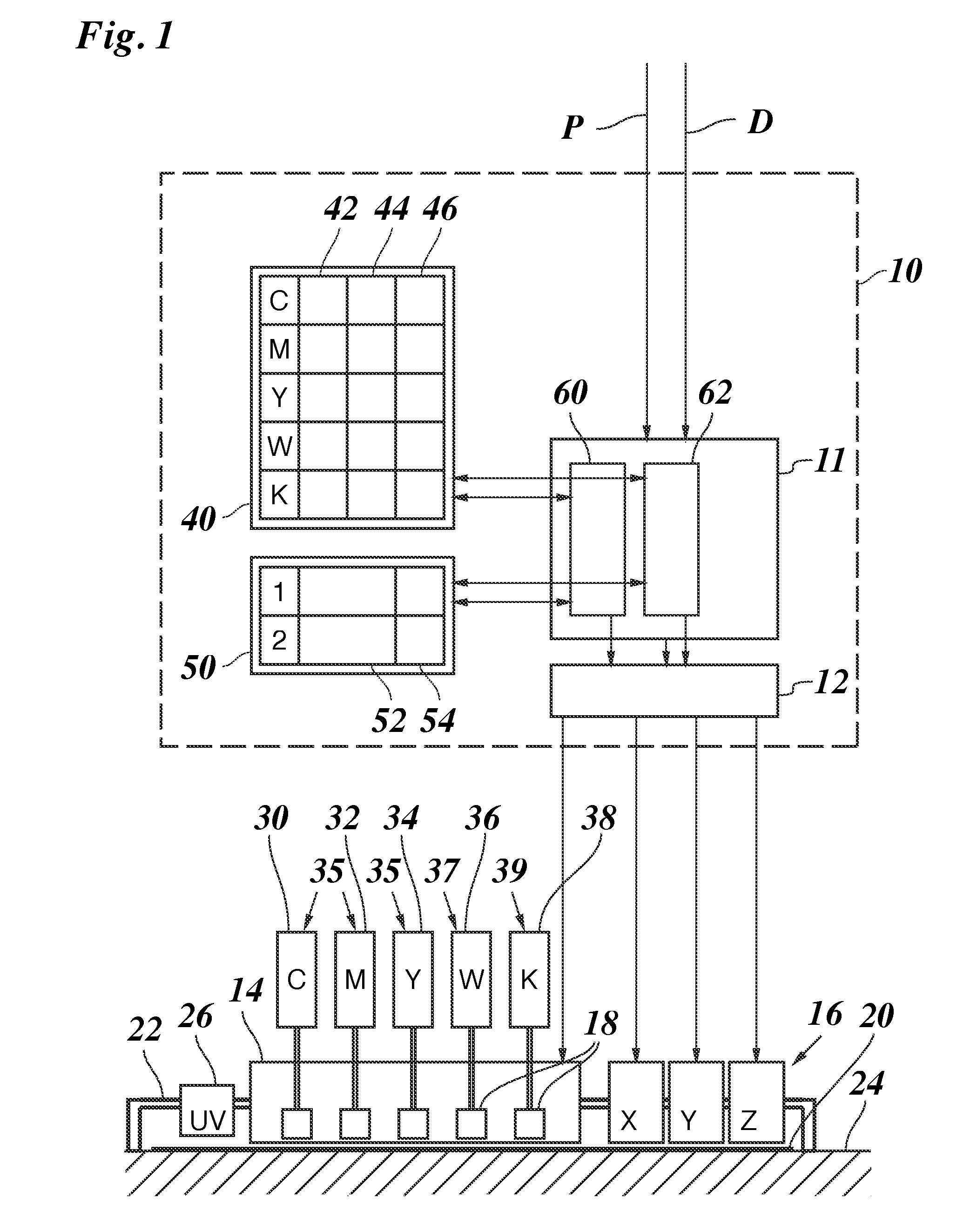
[0070]In a second example, the proportion may be fine tuned to counterbalance the expansion / shrinkage properties of the inks even better. For example, the proportion determining unit 62 may determine a proportion of 22.4% to 77.6% for the amount of the second ink K to the amount of the first inks for the elevation layer. That is, the elevation layer 70 contains 77.6% Océ IJC255 ink and 22.4% Océ IJC256 ink. Therefore, the expansion of the elevation layer 70 is (0.776×−0.4%)+(0.224×2%)=0.1376%.

[0071]As above, the shrinkage of the top layer 71 is 1.0×−0.4%=−0.4%.

[0072]The resulting total curing expansion of the printed structure is: (0.15 / 0.2×0.1376%)+(0.05 / 0.2×−0.4%)=0.003%.

[0073]For example, in order to achieve the above proportion, the raster image processor 12 may use a reduced dot density of 87% for the first inks 35, 37 (C,M,Y,W), and the normal dot density of 100% for the second ink 39 (K) for printing the sub-layers 72 (steps S6, S7).

[0074]As the curing expansion / shrinkage pro...

third example

[0077]FIG. 7 shows a third example. A multilayer structure is printed on a receiving material 20. In this example, the combined effects of the curing expansion / shrinkage properties and thermal expansion of the inks is minimized for a target temperature of e.g. 70° C. For example, the target temperature is a temperature within a usage temperate range of the resulting product. For example, the receiving material 20 is polycarbonate having a linear thermal expansion coefficient of 0.07 mm / m K.

[0078]For example, the linear thermal expansion coefficients of the inks may be measured using e.g. a test strip prepared as explained above with FIG. 6. For example, the linear thermal expansion coefficient of the first ink, Océ IJC255, is: 0.15 mm / m K. The linear thermal expansion coefficient of the second ink, IJC256, is: 0.22 mm / m K.

[0079]Thus, the thermal expansion of the inks relative to the polycarbonate, between a printing temperature of e.g. 40° C. and a target temperature of 70° C. is: (...


PUM

PropertyMeasurementUnit
heightaaaaaaaaaa
heightaaaaaaaaaa
heightaaaaaaaaaa

Abstract

A printing system and a method for printing a multilayer structure using radiation curable ink, the multilayer structure comprising multiple ink layers which are consecutively printed, and wherein a first printed ink layer of any two consecutively printed ink layers is cured before a subsequently printed ink layer is printed thereon, wherein at least one ink of multiple inks is selected for being used for printing the multilayer structure, said multiple inks comprising at least one first and at least one second radiation curable ink, wherein said at least one ink is selected in dependence on information about at least one property of the said at least one ink apart from color, wherein, of the multiple inks, at least the selected at least one ink and at least one of the at least one first ink are used for printing the multilayer structure; the physical property being e.g. an expansion / shrinkage property and / or an adhesion property.

Description

BACKGROUND OF THE INVENTION[0001]1. Field of the Invention[0002]The invention relates to a method of printing a multilayer structure using radiation curable ink. Furthermore, the invention relates to a printing system, in particular an ink jet printing system, for printing a multilayer structure using radiation curable ink.[0003]2. Description of the Related Art[0004]WO 2008 / 077850 A2 describes a 3D-inkjet printing method comprising the steps of: providing two or more fluids having a different composition to an inkjet printer; mixing the two or more fluids in a controlled amount; and jetting the mixture of the two or more fluids with the inkjet printer onto a support; at least partially curing the jetted mixture by actinic radiation or electron beam; and repeating the steps of mixing, jetting and curing in order to build a 3D-relief on the support. In one example, the composition of mixture made in the mixing step is changed at least once for the step of repeating the steps.[0005]WO...

Claims


Application Information

Patent Timeline
Patent Type & Authority Patents(United States)
IPC IPC(8): B41J29/38B41J11/00B41M7/00B29C67/00B41M5/00B33Y10/00B41M3/16B41M3/00B33Y30/00
CPCB41J29/38B29C67/0059B41J11/002B41J11/0015B41M5/0047B41M5/0064B41M7/0081B33Y10/00B33Y30/00B41M3/008B41M3/16B29C64/112B41J11/0021
Inventor WEIJKAMP, CLEMENS T.
Owner OCE TECH
Learn More