
Fluid ejection using MEMS composite transducer

a composite transducer and flue gas technology, applied in the direction of printing, other printing apparatus, etc., can solve the problems of not being able to provide the range of performance desired, not being able to provide the independent operation of mems transducers, and not being able to provide the sealing cavity of typical mems transducer designs

Inactive Publication Date: 2012-10-25
EASTMAN KODAK CO
View PDF22 Cites 3 Cited by
  • Summary
  • Abstract
  • Description
  • Claims
  • Application Information

AI Technical Summary

Benefits of technology

[0005]Accordingly, there is an ongoing need to provide a fluid ejector that includes a MEMS transducer design and method of operation that facilitates low cost fluid ejecting devices having improved volumetric displacement, provides an ejection force increases spatial compactness of an array of fluid ejectors, or increases ejector compatibility with fluids having different fluid properties.
[0009]For either page-width printers or carriage printers, there is an ongoing need to provide a printhead having arrays of large numbers of fluid ejectors arranged in a relatively small space. Accordingly, there is also an ongoing need to provide a fluid ejector that is spatially compact and is capable of ejecting a drop a required size, and that provides sufficient force at an appropriate operating frequency to eject high viscosity inks, such as nonaqueous inks. Additionally, for ejecting some types of inks, there is an ongoing need to provide a fluid ejecting mechanism that does not impart excessive heat into the inks (that in some instances also requiring subsequent cooling) so as to increase ink compatibility and facilitate increased drop ejection frequency.
[0010]In addition to conventional printing applications, fluid ejectors can be used for ejection of other types of materials. For ejecting materials that can be damaged by excessive heat, there is an ongoing need to provide a fluid ejector that does not apply excessive heat to the fluid being ejected so as to minimizes the likelihood of properties of the fluid changing during drop ejection.SUMMARY OF THE INVENTION

Problems solved by technology

Based on material properties and geometries commonly used for MEMS transducers the amount of deflection can be limited, as can the frequency range, so that some types of desired usages are either not available or do not operate with a preferred degree of energy efficiency, spatial compactness, or reliability.
For some applications independent operation of MEMS transducers is not able to provide the range of performance desired.
Further, typical MEMS transducer designs do not provide a sealed cavity which can be beneficial for some fluidic applications.
In a fluid ejector that includes a mechanical actuator, for example, a conventional piezoelectric actuator, standing waves can be undesirably set up in the substrate, which interferes with reliable fluid ejection.

Method used


Image

  • Fluid ejection using MEMS composite transducer
  • Fluid ejection using MEMS composite transducer
  • Fluid ejection using MEMS composite transducer

Examples


Embodiment Construction

[0035]The present description will be directed in particular to elements forming part of, or cooperating more directly with, apparatus in accordance with the present invention. It is to be understood that elements not specifically shown or described may take various forms well known to those skilled in the art.

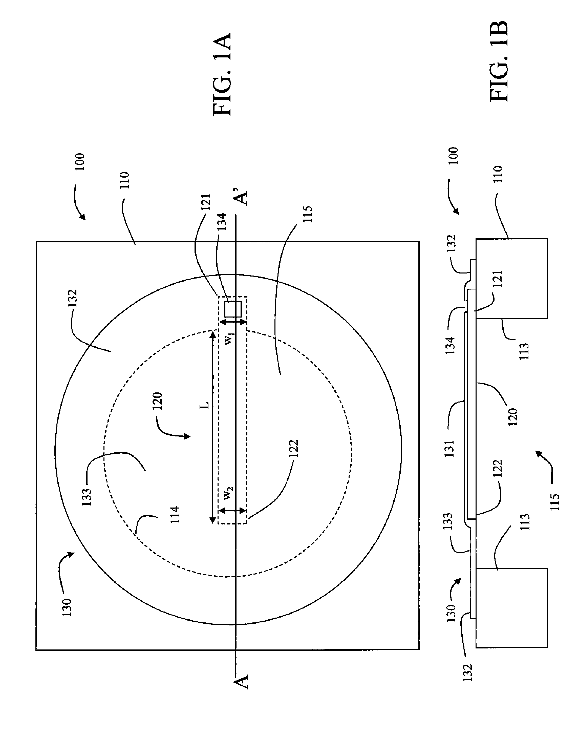
[0036]Embodiments of the present invention include a variety of types of fluid ejectors incorporating MEMS transducers including a MEMS transducing member and a compliant membrane positioned in contact with the MEMS transducing member. It is to be noted that in some definitions of MEMS structures, MEMS components are specified to be between 1 micron and 100 microns in size. Although such dimensions characterize a number of embodiments, it is contemplated that some embodiments will include dimensions outside that range. Typically, the fluid ejectors of the present invention eject liquid, in the form of drops, when a liquid drop is desired.

[0037]FIG. 1A shows a top view and FIG....


PUM


Abstract

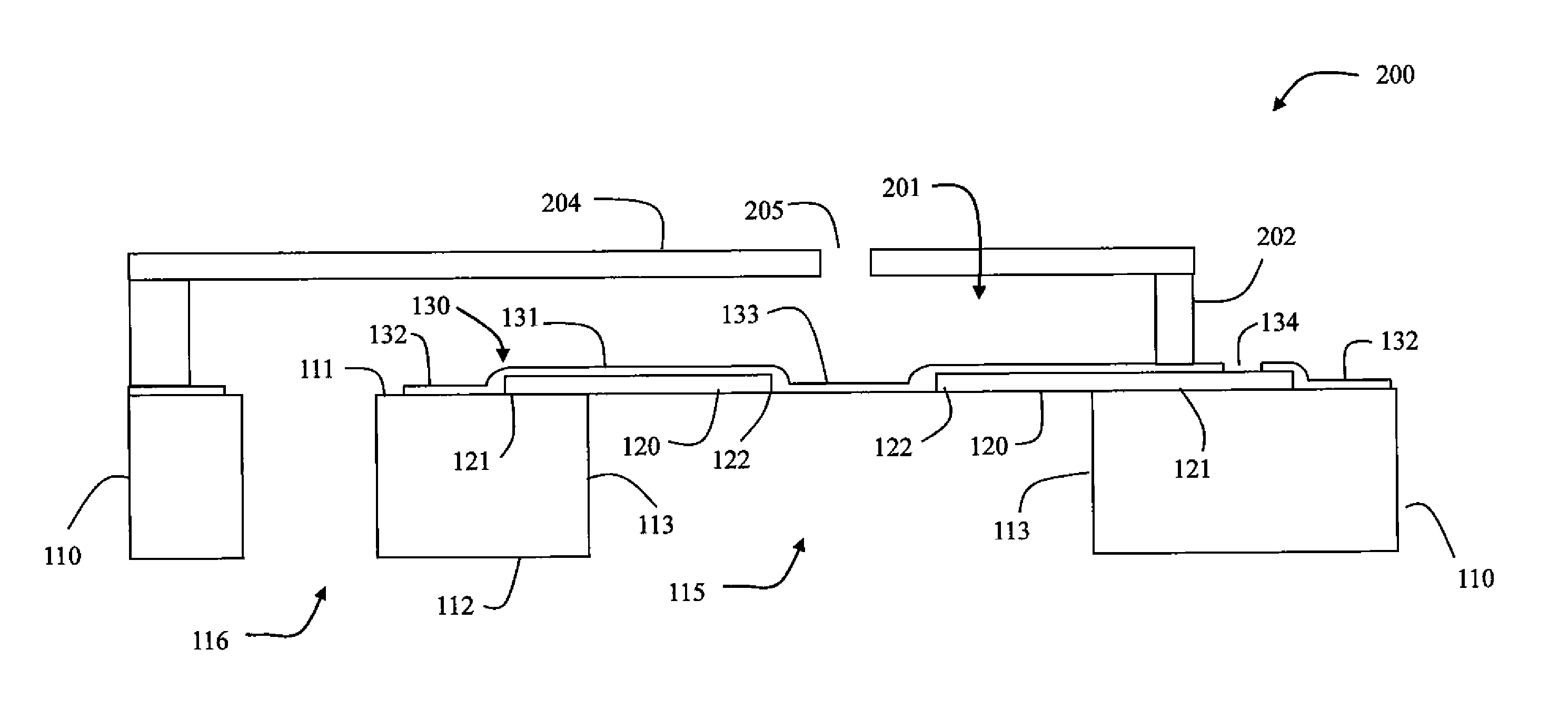
A method of ejecting a drop of fluid includes providing a fluid ejector. The fluid ejector includes a substrate, a MEMS transducing member, a compliant membrane, walls, and a nozzle. The substrate includes a cavity and a fluidic feed. A first portion of the MEMS transducing member is anchored to the substrate. A second portion of the MEMS transducing member extends over at least a portion of the cavity and is free to move relative to the cavity. The compliant membrane is positioned in contact with the MEMS transducing member. A first portion of the compliant membrane covers the MEMS transducing member, A second portion of the compliant membrane being anchored to the substrate. Walls define a chamber that is fluidically connected to the fluidic feed. At least the second portion of the MEMS transducing member is enclosed within the chamber. A quantity of fluid is supplied to the chamber through the fluidic feed. An electrical pulse is applied to the MEMS transducing member to eject a drop of fluid through the nozzle.

Description

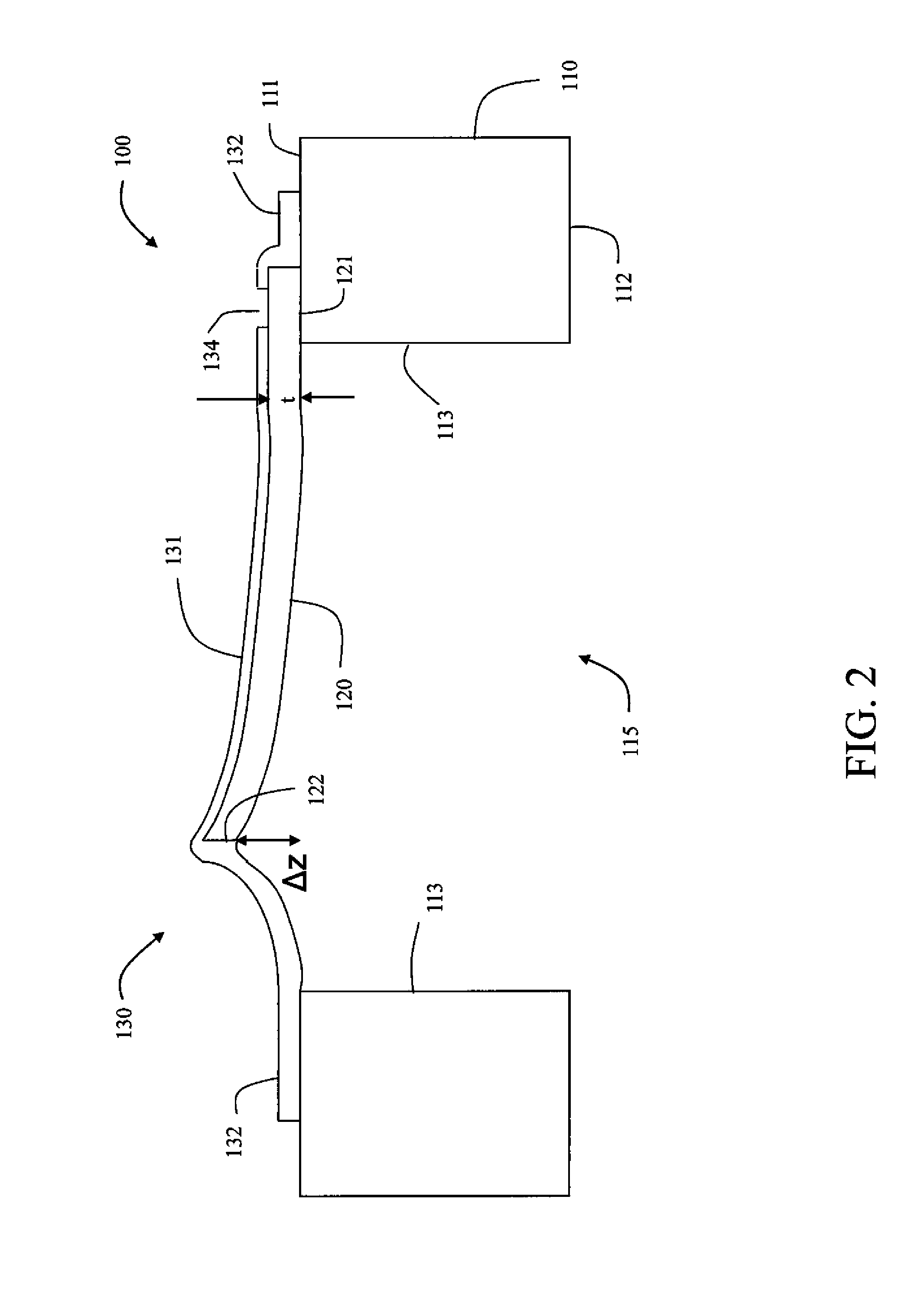
[0001]Actuators can be used to provide a displacement or a vibration.[0002]For example, the amount of deflection δ of the end of a cantilever in response to a stress σ is given by Stoney's formulaδ=3σ(1−v)L2 / Et2  (1),where v is Poisson's ratio, E is Young's modulus, L is the beam length, and t is the thickness of the cantilevered beam. In order to increase the amount of deflection for a cantilevered beam, one can use a longer beam length, a smaller thickness, a higher stress, a lower Poisson's ratio, or a lower Young's modulus. The resonant frequency of vibration of an undamped cantilevered beam is given byf=ω0 / 2π=(k / m)1 / 2 / 2π  (2),where k is the spring constant and m is the mass. For a cantilevered beam of constant width w, the spring constant k is given byk=Ewt3 / 4L3  (3).It can be shown that the dynamic mass m of an oscillating cantilevered beam is approximately one quarter of the actual mass of ρwtL (ρ being the density of the beam material), so that within a few percent, the reso...

Claims


Application Information

Patent Timeline
Patent Type & Authority Applications(United States)
IPC IPC(8): B41J29/38B41J2/045
CPCB41J2/14427B41J2/14201B41J2/14282B41J2/14314
Inventor HUFFMAN, JAMES D.DELAMETTER, CHRISTOPHER N.TRAUERNICHT, DAVID P.
Owner EASTMAN KODAK CO
Learn More