Floating wind turbine

a wind turbine and floating technology, applied in the direction of motors, hulls, vessels moving by mass displacement, etc., can solve the problems of limiting factors, complicated and limited factors, and embodiments are therefore unsuitable for assembling and later maintenance on shore, so as to reduce the buoyancy and stability of the hull

Active Publication Date: 2016-10-11
WINDEL GMBH & CO KG
View PDF14 Cites 1 Cited by
  • Summary
  • Abstract
  • Description
  • Claims
  • Application Information

AI Technical Summary

Benefits of technology

[0036]The above embodiment differs from generally known embodiments with floating columns for wind turbines e.g. of the kind which is known from Hywind and Sway, in that it has a surrounding floating frame which in a normal position is securely connected with the hull and thereby contributes with buoyancy and stability to the hull in such a way that the inherent buoyancy and stability of the hull may be reduced accordingly. Hywind is a floating ocean wind turbine where the construction comprises a steel cylinder filled with a ballast of water and stones. It extends approximately 100 meter down into the sea and is moored to the sea floor. Sway is a floating construction which is anchored to the sea floor by tension le

Problems solved by technology

This solution and similar solutions have in common that installation of supporting column and wind turbine, and also later maintenance and repair, must take place at open sea by means of large and costly crane vessels, where weather and wave conditions may be a complicating and limiting factor.
Embodiments with floating col

Method used


Image

  • Floating wind turbine
  • Floating wind turbine
  • Floating wind turbine

Examples


Embodiment Construction

[0048]Position and situation designations, like e.g. right, left, upper, lower, vertical, horizontal, refers to the position illustrated in the figures.

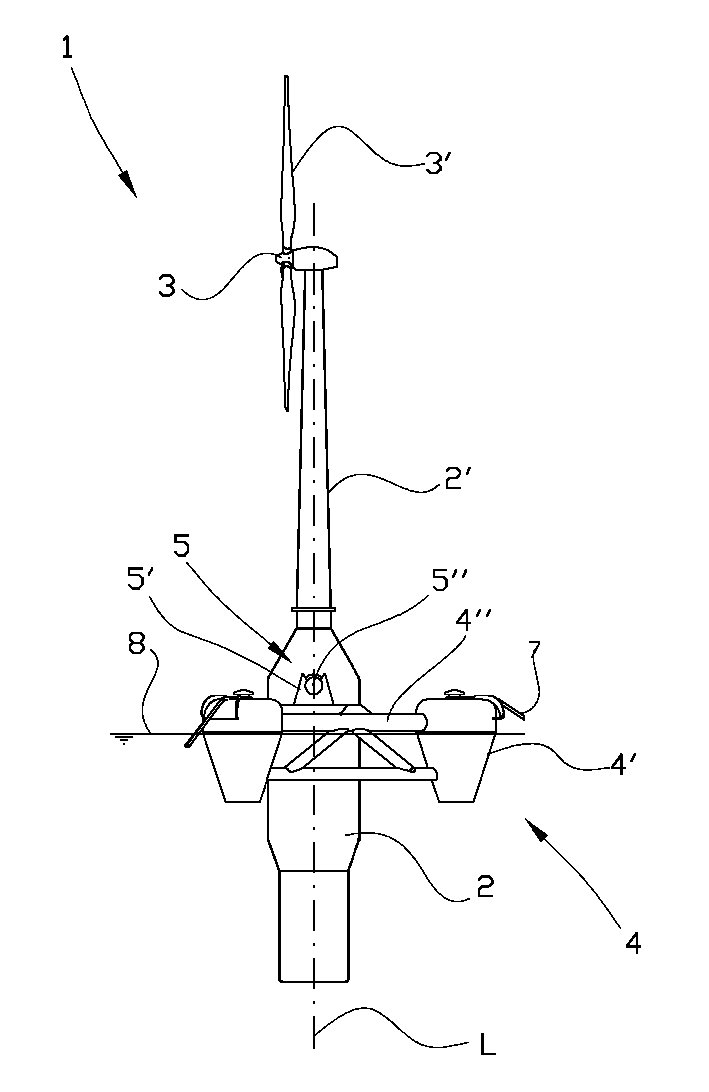
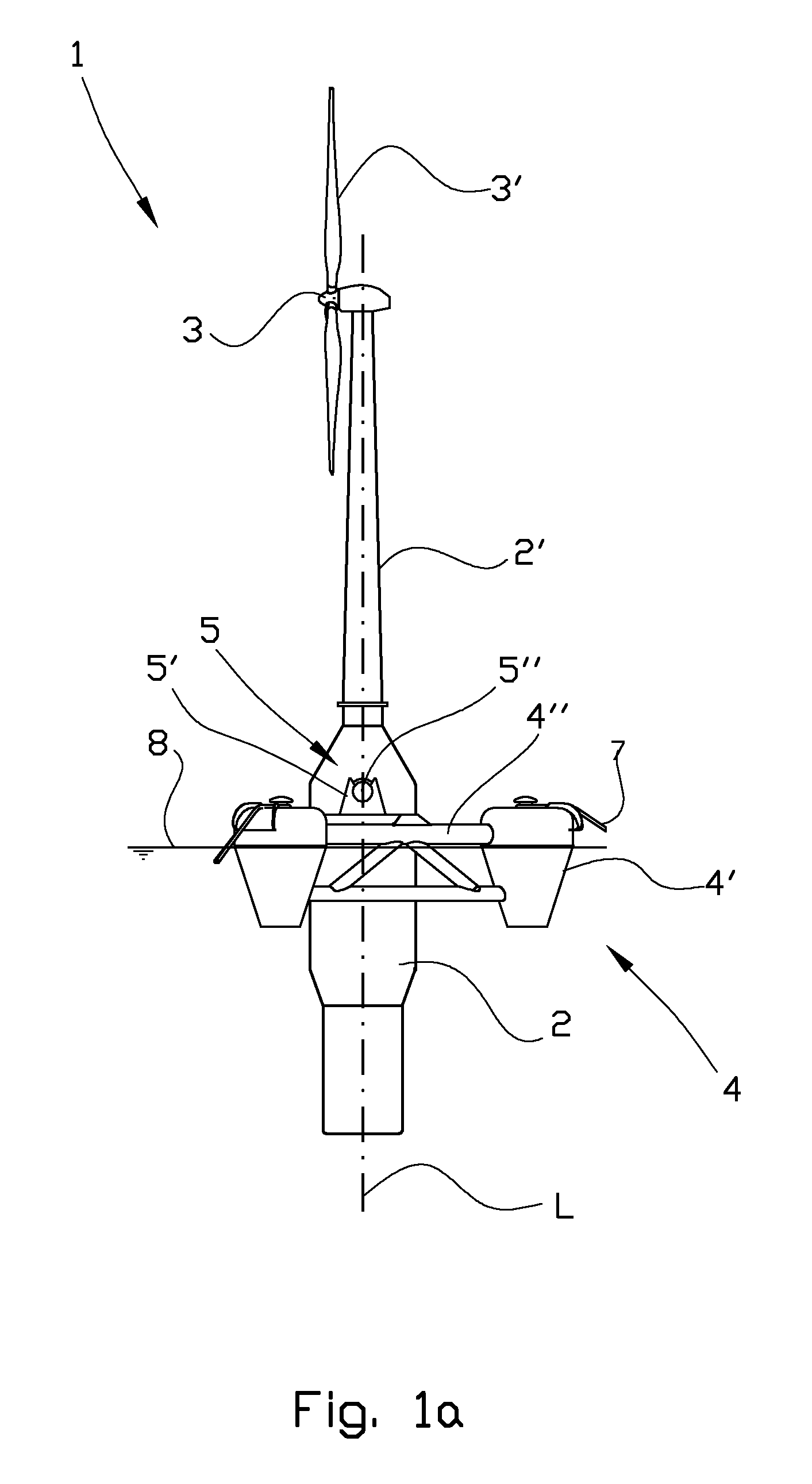
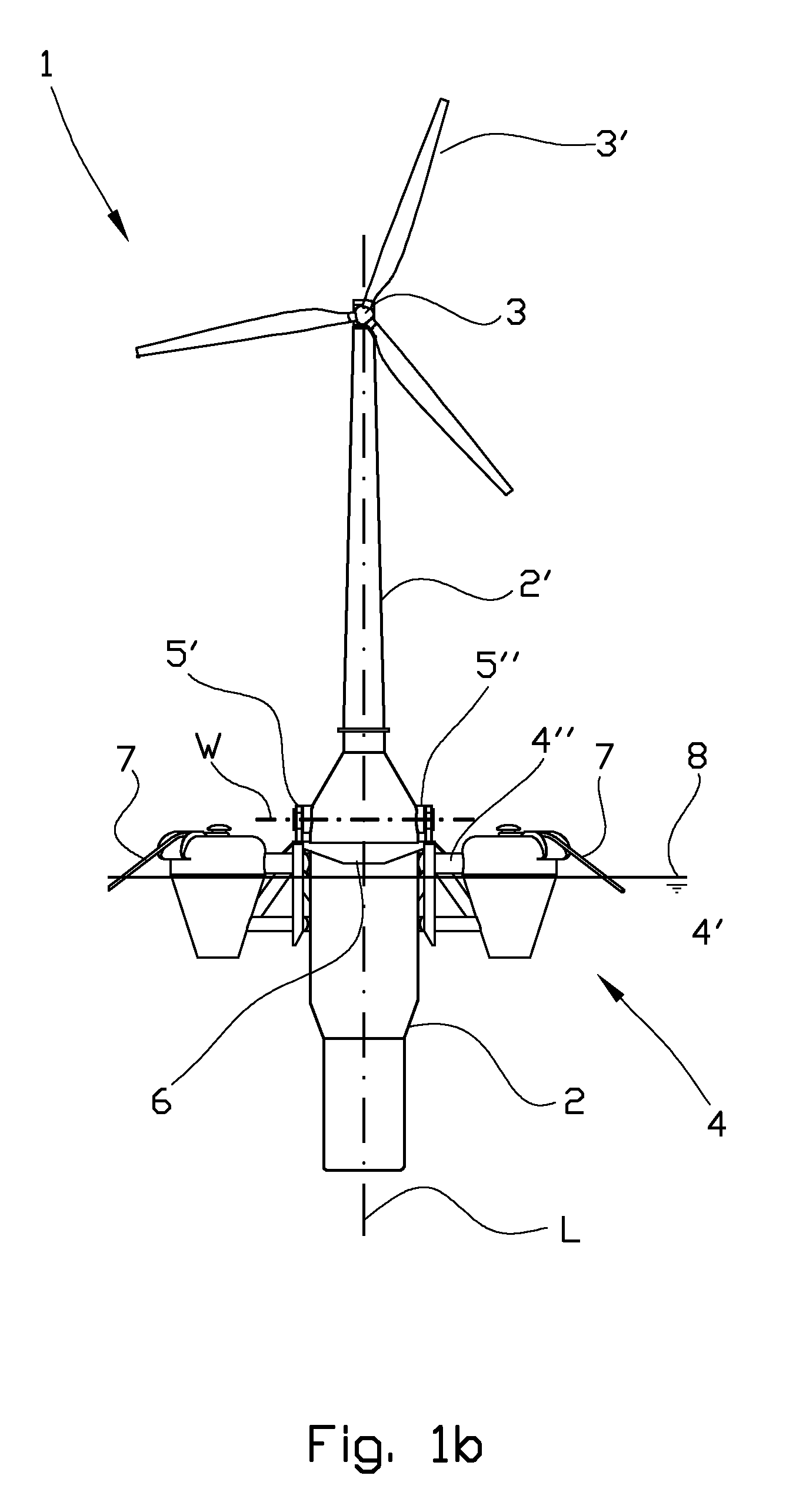
[0049]In the figures reference numeral 1 denotes a wind turbine for electric power production. The wind turbine 1 comprises a hull 2 attached to a supporting column 2′. In the upper portion of the supporting column 2′ there is arranged a wind turbine 3, which in a per se known way is arranged to be put into rotation by wind acting on three rotor blades 3′.

[0050]The wind turbine 1 is connected to a buoyancy device 4 which is arranged to be able to support a least a portion of the mass of the wind turbine 1, in addition to the mass of the buoyancy device 4 and also the mass of mooring devices 7 forming a part of a mooring system which will be well known to a person skilled in the art, and for that reason will not be described more closely in this document.

[0051]The buoyancy device 4 includes in the illustrated embodiment three buoyancy...


PUM

PropertyMeasurementUnit
Weightaaaaaaaaaa
Angleaaaaaaaaaa
Massaaaaaaaaaa

Abstract

A floating wind turbine (1) for electric power production and a method for use of the wind turbine (1) is described. The wind turbine (1) includes a hull (2) attached to a supporting column (2′) for a wind turbine (3) arranged to be put into rotation by wind force acting on rotor blades (3′). The wind turbine (1) is connected to a buoyancy device (4) by a coupling device (5). The buoyancy device (4) encircles at least a portion of the hull (2) and supports at least a portion of the mass of the wind turbine (1). The coupling device (5) is a rotary coupling arranged in such a way that the wind turbine (1) is able to rotate an angle from an essentially vertical position towards a horizontal position, or the opposite. The hull (2) is provided with an adjustable ballast (9, 12) arranged to balance the wind turbine (1) about the rotary coupling (5) in any position between the positions.

Description

CROSS-REFERENCE TO RELATED APPLICATION[0001]This United States National Phase of PCT Application No. PCT / NO2012 / 050183 filed 25 Sep. 2012, claims priority to Norwegian Patent Application No. 20111329 filed 29 Sep. 2011, each of which are incorporated herein by reference.STATEMENT REGARDING FEDERALLY SPONSORED RESEARCH OR DEVELOPMENT[0002]Not Applicable.NAMES OF PARTIES TO A JOINT RESEARCH AGREEMENT[0003]Not Applicable.INCORPORATION-BY-REFERENCE OF MATERIAL SUBMITTED ON A COMPACT DISC OR AS A TEXT FILE VIA THE OFFICE ELECTRONIC FILING SYSTEM[0004]Not Applicable.BACKGROUND OF THE INVENTION[0005]The present invention relates to a floating wind turbine and a method for controlling the vertical extent of the wind turbine. More particularly it relates to a floating windmill for electric power production, the windmill comprises a hull attached to a supporting column for a wind turbine which is arranged to be put into rotation by wind force acting on rotor blades, the wind turbine is connec...

Claims


Application Information

Patent Timeline
IPC IPC(8): E04H12/18F03D1/00E04H12/34
CPCF03D13/25E04H12/187E04H12/345F03D1/001F03D1/005F03D13/20F05B2230/60F05B2240/9152F05B2240/93F05B2240/95F05B2250/11Y02E10/727Y02E10/728Y10T29/49316B63B1/107B63B39/03B63B2035/446B63B77/10F03D9/25F03D13/10F03D13/40Y02E10/72Y02P70/50
Inventor TOLO, MAGNE
Owner WINDEL GMBH & CO KG
Why Eureka
Try Eureka