
Image processing device and image processing method

a technology of image processing and image, applied in image enhancement, tomography, instruments, etc., can solve the problems of difficult to obtain the target image, erroneously detect strong streak artifacts,

Active Publication Date: 2016-09-27
FUJIFILM HEALTHCARE CORP
View PDF18 Cites 1 Cited by
  • Summary
  • Abstract
  • Description
  • Claims
  • Application Information

AI Technical Summary

Benefits of technology

This approach allows for the generation of a target image that effectively maintains the edge of structures and removes streak artifacts, preventing incorrect classification and blurring, thus improving diagnostic image quality.

Problems solved by technology

Then, in a case where detection of the edge is performed by using the difference between the maximum value and the minimum value of the values of the pixels in the predetermined region including the pixel of interest, and the variance value, the concentration gradient and so forth thereof as in the technique described in Japanese Patent No. 3700798, the possibility that the strong streak artifact may be erroneously detected as the edge is high.
That is, it is difficult to obtain the target image by the techniques described in Japanese Patent No. 3700798) and Japanese Patent Application Laid-Open No.

Method used


Image

  • Image processing device and image processing method
  • Image processing device and image processing method
  • Image processing device and image processing method

Examples


first embodiment

[First Embodiment]

[0054]In the following, the first embodiment of the present invention will be described following the stream of a processing flow illustrated in FIG. 4 while appropriately referring to other drawings.

101>

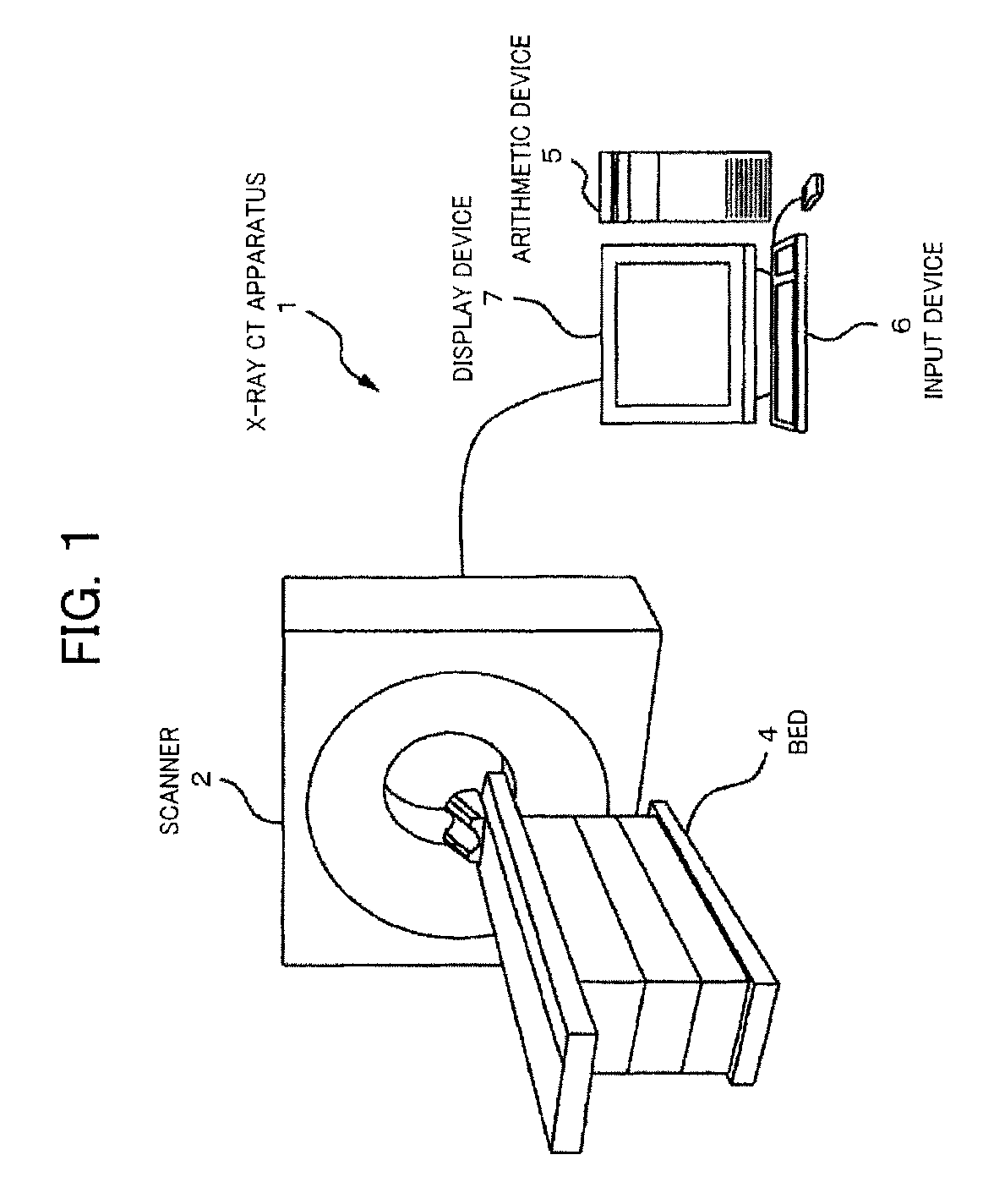
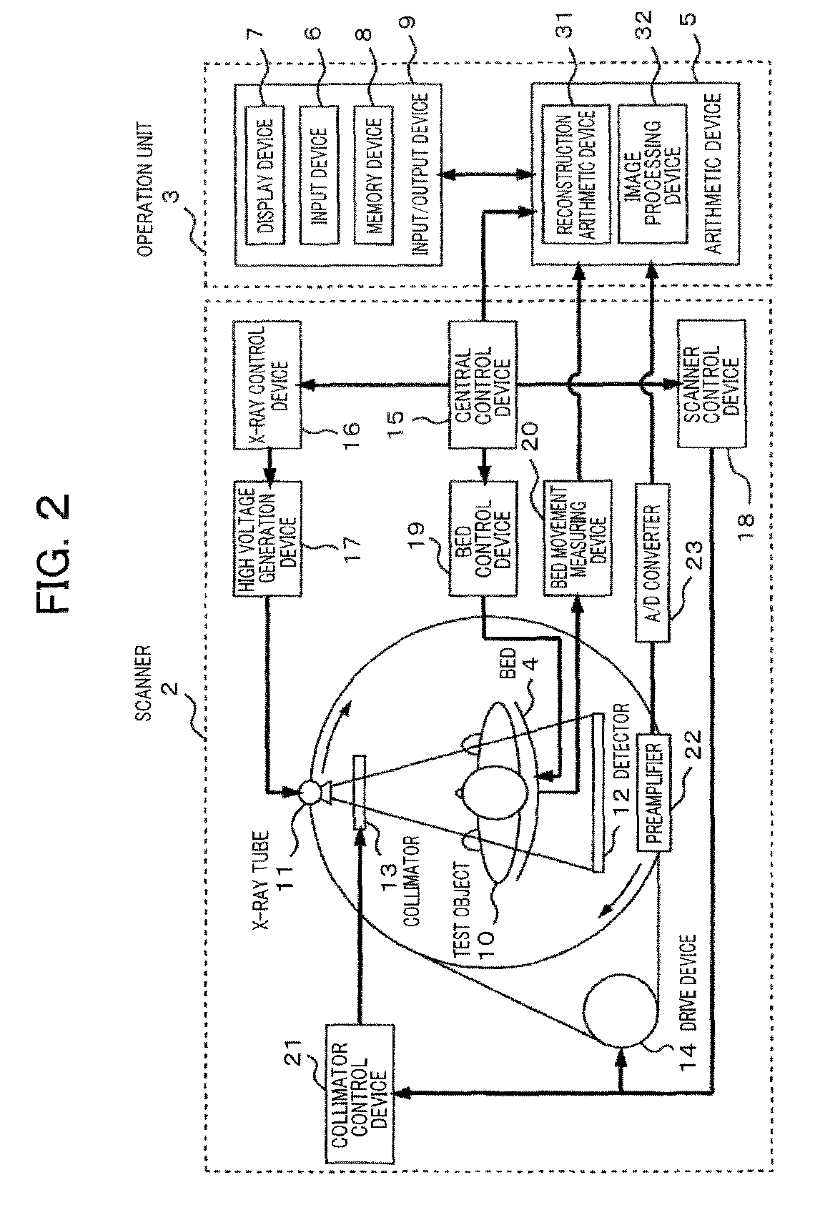
[0055]The arithmetic device 5 of the X-ray CT apparatus 1 (hereinafter, referred to as the “arithmetic device 5) determines the shape of the nonlinear function on the basis of feature amounts of the original image and the smoothed image. A process of determining the shape of the nonlinear function will be described later with reference to FIG. 5.

201>

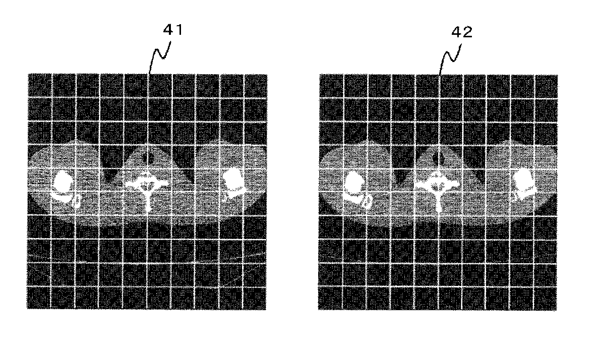
[0056]The arithmetic device 5 divides regions of the original image and the smoothed image into mutually corresponding small regions. For example, as illustrated in FIG. 6, the arithmetic device 5 partitions the regions of an original image 41 and a smoothed image 42 in a lattice shape and divides them into small regions. The size of the small region is empirically determined.

[0057]However, the method of dividing one re...

second embodiment

[Second Embodiment]

[0091]In the following, the second embodiment of the present invention will be described. Incidentally, description of the contents which are common to the first embodiment is omitted.

[0092]In the first embodiment, the small region whose decreasing rate of the variation value of the smoothed image 42 to the variation value of the original image 41 has the maximum value is extracted as the feature amount calculation region and the parameter ν for adjusting the bending position of the nonlinear function is determined on the basis of the feature amount of the feature amount calculation region. At that time, the feature amount calculation region is extracted by analyzing in more detail the relation between the decreasing rate of the variation value and the variation value of the original image 41 or the smoothed image 42. Owing to this, the precision that the flat region including the streak artifact 51 is extracted as the feature amount calculation region is improved...


PUM


Abstract

In order to provide an image processing device and the like making it possible to generate a target image in which edges of a structure are upheld and from which streaking artifacts are removed, a computation device determines a shape of a non-linear function on the basis of feature amounts of an original image and a smoothed image (S101). Next, the computation device calculates a condition coefficient of the original image and the smoothed image by using the non-linear function for which the shape was determined in S101 (S102). Next, the computation device uses the condition coefficients calculated in S102 to calculate a weighting coefficient for each of the pixels of the original image and the smoothed image (S103). Next, the computation device adds weighting to the original image and the smoothed image to generate the target image (S104).

Description

BACKGROUND OF THE INVENTION[0001]1. Field of the Invention[0002]The present invention relates to an image processing device that performs image processing on an image obtained by using an X-ray CT apparatus and so forth, and more particularly relates to a technology that maintains an original shape of the edge of a structure and removes streak artifacts.[0003]2. Description of the Related Art[0004]In an image reconstructing method, the X-ray CT apparatus reconstructs a tomographic image of a test object by irradiating the test object with X-rays from around the object and back-projecting real projection data acquired at a plurality of projection angles.[0005]When an image of flat body part such as the shoulder and so forth of the test object is to be reconstructed on the basis of original information obtained by such an X-ray CT apparatus as aforementioned, in a case where an exposure dose of the X-rays is insufficient, the streak artifacts are generated in a direction which is larg...

Claims


Application Information

Patent Timeline
Patent Type & Authority Patents(United States)
IPC IPC(8): G06T5/00A61B6/03G06T11/00G06T5/50A61B6/00
CPCG06T5/002A61B6/032A61B6/5205G06T5/005G06T5/50G06T11/008G06T2207/10081G06T2207/20224G06T2207/30004G06T2211/40G06T5/77G06T5/70
Inventor TAKAHASHI, HISASHIHIROKAWA, KOICHIGOTO, TAIGA
Owner FUJIFILM HEALTHCARE CORP
Learn More