Device for measuring knee laxity

a technology for measuring knee laxity and knee joint, which is applied in the field of knee laxity measuring devices, can solve the problems of inability to use inside mri or cat-scan devices, interfere with image processing, and not allow an accurate diagnosis of associate instabilities

Active Publication Date: 2016-09-27
FJR SGPS
View PDF8 Cites 1 Cited by
  • Summary
  • Abstract
  • Description
  • Claims
  • Application Information

AI Technical Summary

Benefits of technology

[0031]The present invention can be placed inside a MRI or CAT-scan device to help measuring the laxity of a knee with ligament rupture, in order to obtain one or more images of antero-posterior translation.
[0032]Therefore, a rotation will be executed, which may be measured between two bony points on the tibia and femur with high precision, the measurement being performed on the image without distortion since the materials used will be tested in order not to interfere with the image.

Problems solved by technology

Ferromagnetic materials are used in these devices, what makes them unusable inside MRI or CAT-scan devices is they interfere with the image processing.
On account of this uniqueness, it doesn't allow an accurate diagnosis of associate instabilities.
On account of those limitations, the device disclosed in patent EP 1 125 567 does not allow distinction of those patients who need a surgical technique with greater or lesser rotation control, and also does not allow the evaluation of patients with associate ligament injuries (most common).

Method used


Image

  • Device for measuring knee laxity
  • Device for measuring knee laxity
  • Device for measuring knee laxity

Examples


Embodiment Construction

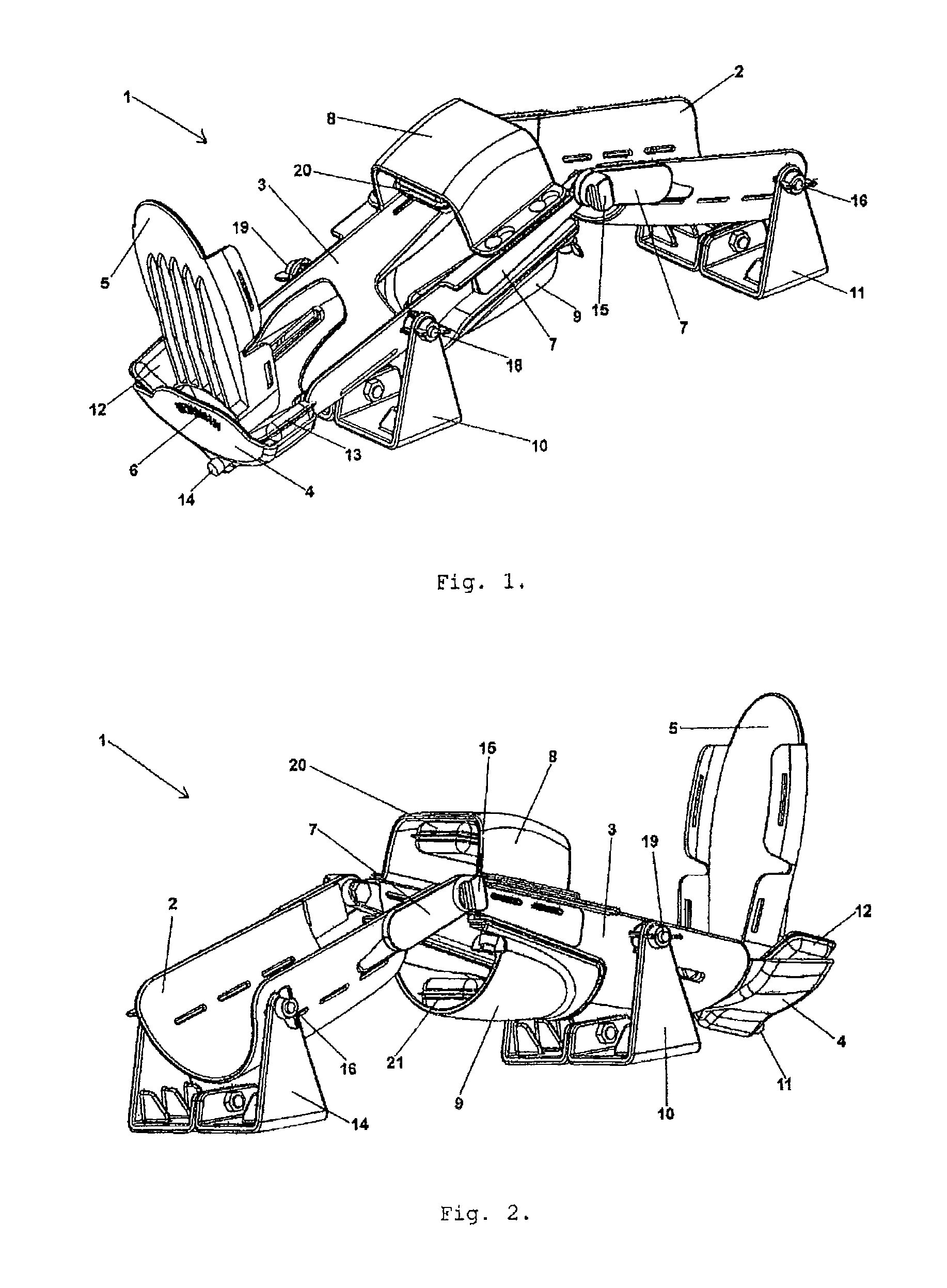
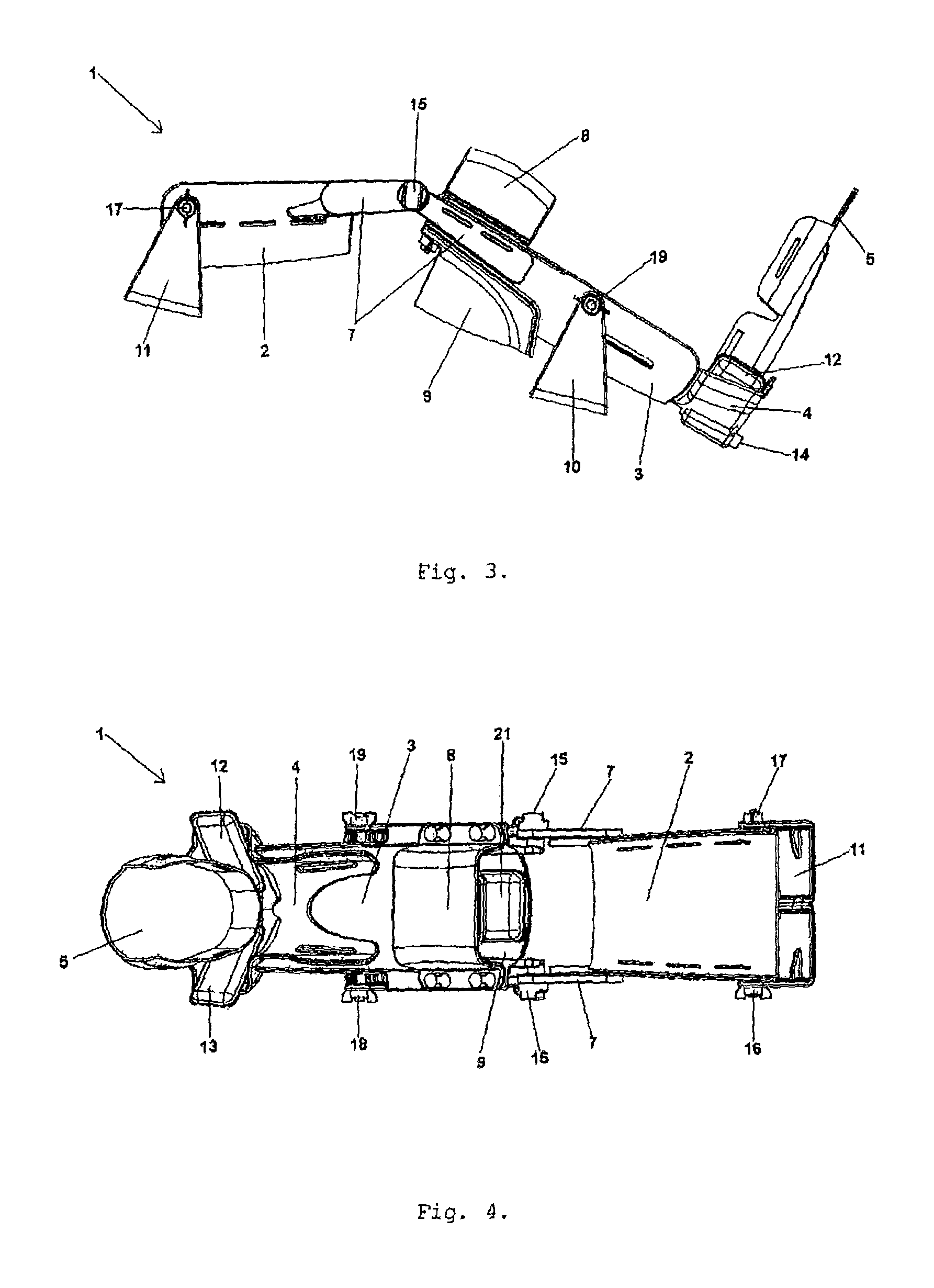
[0059]As can be seen in FIGS. 1, 2, 3 and 4, the device (1) described in this invention is comprised essentially of four parts, namely a part (2) for the posterior support and fixation of the thigh, a part (3) for the posterior support and fixation of the leg, a supporting part (4) and a part (5) for posterior support and fixation of the foot.

[0060]These four parts respectively include multiple belts, not represented in the figures, which together with parts (8) and (9) will ensure that the leg, thigh and foot lay and remain fixed against the device (1), object of this invention.

[0061]To ensure that the images obtained with the device (1) by computed axial tomography scan or magnetic resonance imaging do not show distortions, all materials used in the present invention are plastics, resins and composites.

[0062]The device (1) comprises independent means (20) to push backwards the anterior zone of the leg and means (21) to push forward the posterior zone of the leg (21), shown in FIG....


PUM


Abstract

The present invention relates to a device (1) for measuring the knee laxity, with or without use of additional means of diagnosis such as computed axial tomography and magnetic resonance imaging, evaluating the instability of the knee due to rupture of any ligament, namely the anterior cruciate ligament, posterior cruciate ligament, postero-internal capsule, postero-external capsule, as well as around the axis of an orthonormal referential, that comprises three parts respectively to accept and retain the thigh, leg and foot.The device (1) includes independent means (20) and (21) to push backward the anterior zone of the leg and to push forward the posterior zone of the leg, and independent means (12) and (13) to push the part (5) for support and fixation of the foot in clockwise direction and in anti-clockwise direction.

Description

FIELD OF THE INVENTION[0001]The present invention relates to a device for evaluating the instability of the knee due to rupture of any ligament, namely the anterior cruciate ligament, posterior cruciate ligament, postero-internal capsule, postero-external capsule, as well as in all the axis of orthonormal, anterior, posterior, antero-internal, antero-external, postero-internal and postero-external referentials.[0002]In recent decades, the number of injuries in lower limb joints has significantly increased. This problem affects both athletes and any other individuals who may be victims of accidents and / or congenital diseases.[0003]This type of injuries and traumas leads to an individual inability since it creates instability of the knee, preventing their normal functions (rotation, impulse and extension) thus creating an incapacity for the individual to execute his daily tasks.[0004]In fact, the treatment of the knee ligaments ruptures varies depending on the severity and can involve...

Claims


Application Information

Patent Timeline
Patent Type & Authority Patents(United States)
IPC IPC(8): A61B5/00A61B6/03A61B5/055A61B5/103A61B5/11
CPCA61B5/4585A61B5/055A61B5/103A61B5/1107A61B5/1121A61B5/4528A61B5/70A61B6/03A61B5/6812A61B5/6828A61B5/6829A61B2503/10A61B2505/05A61B5/11
Inventor COELHO DO SAMEIRO ESPREGUEIRA MENDES, JOAO
Owner FJR SGPS
Why Eureka
Try Eureka