Sheet conveying apparatus and image forming apparatus

a technology of conveying apparatus and sheet, applied in the direction of transportation and packaging, electrographic process, instruments, etc., can solve the problems of sheet alignment failure, subsequent sheet may not be received, etc., and achieve the effect of high precision

Inactive Publication Date: 2016-09-20
CANON KK
View PDF24 Cites 6 Cited by
  • Summary
  • Abstract
  • Description
  • Claims
  • Application Information

AI Technical Summary

Benefits of technology

[0015]According to the invention, even when there are diverse shift amounts between the precedent sheet and the subsequent sheet which are being conveyed, it is possible to control the shift amount of the sheet with high precision.

Problems solved by technology

In an existing sheet post-processing device with a post-processing unit such as a stapler, a subsequent sheet may not be received during the execution of sheet post-processing of a precedent sheet since it takes time for the sheet post-processing such as aligning and stapling.
At this time, if the shift amount of two sheets increases, even when the lower precedent sheet first abuts the reference wall, the upper subsequent sheet stops without reaching the reference wall, and hence there is a problem in that an aligning failure of the sheet occurs.

Method used


Image

  • Sheet conveying apparatus and image forming apparatus
  • Sheet conveying apparatus and image forming apparatus
  • Sheet conveying apparatus and image forming apparatus

Examples


first embodiment

[First Embodiment]

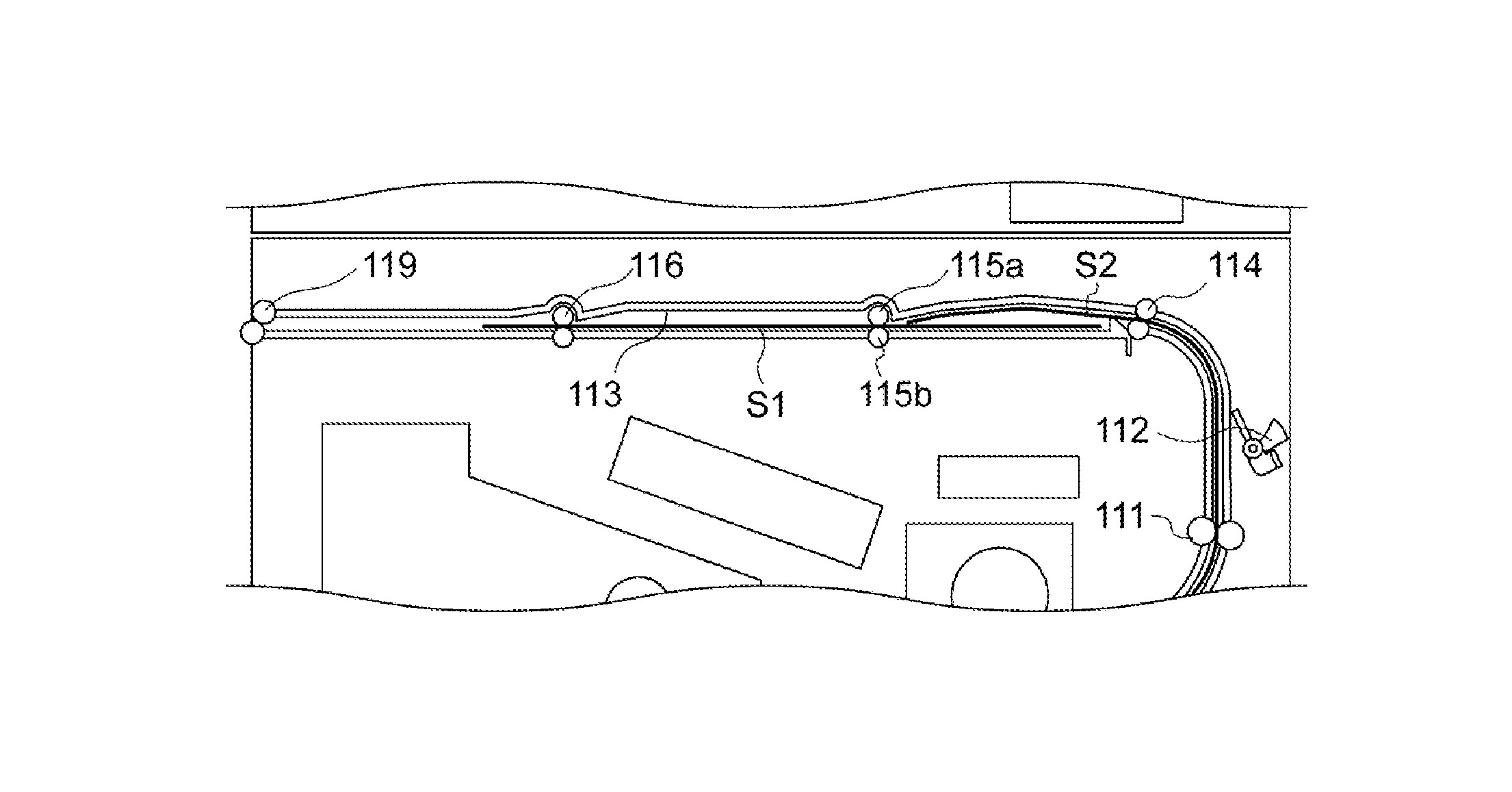
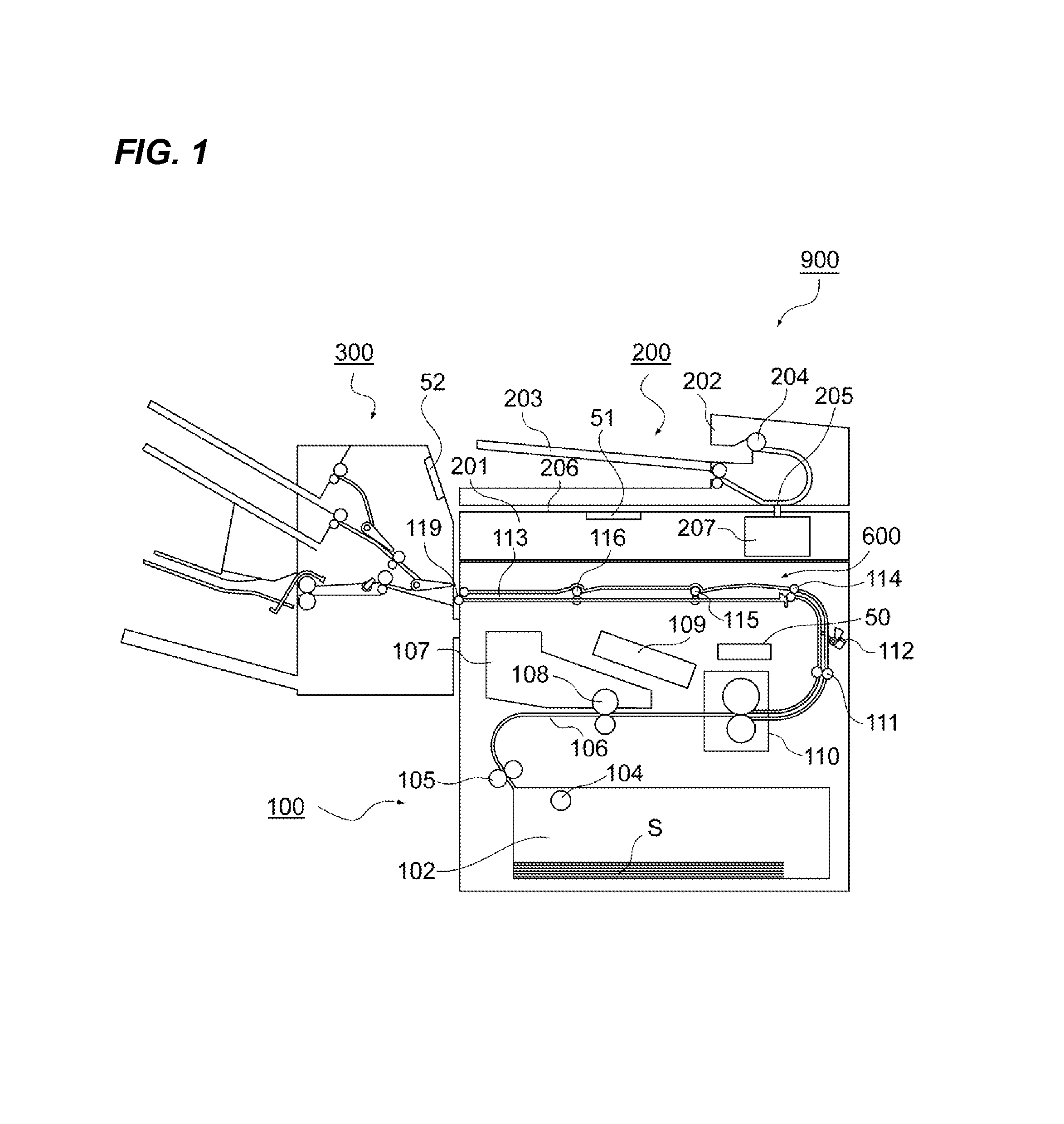
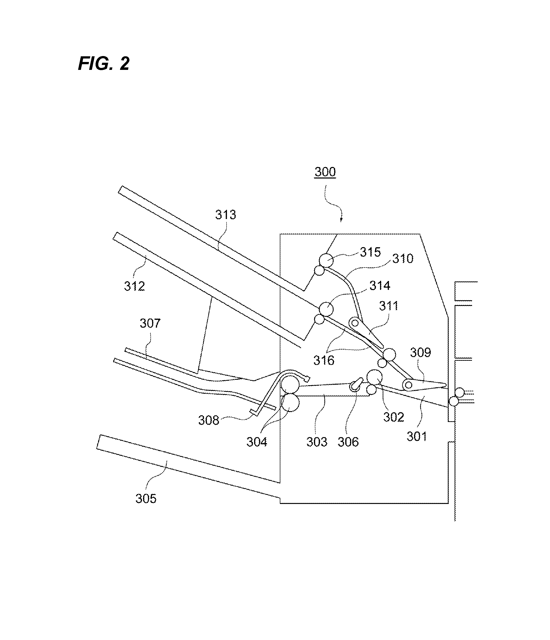
[0028]FIG. 1 is a cross-sectional view illustrating a configuration of an image forming apparatus 900 according to a first embodiment of the invention. The image forming apparatus 900 is an image forming apparatus which uses an electrophotographic image forming process. As illustrated in FIG. 1, the image forming apparatus 900 includes an image forming apparatus body (hereinafter, simply referred to as an “apparatus body”) 100, an image reading unit 200 which is disposed above the apparatus body 100, and a sheet post-processing device 300 which serves as a “sheet post-processing unit” connected to the side surface of the apparatus body 100. The apparatus body 100 includes therein an image forming process unit 107 which serves as an “image forming unit” for forming an image. The image forming unit includes a photosensitive drum 108 which serves as an “image bearing member”, a transfer roller which serves as a “transfer device”, and the like.

[0029]The image reading u...

second embodiment

[Second Embodiment]

[0073]FIG. 8 is a cross-sectional view illustrating a configuration of a sheet conveying apparatus 700 according to a second embodiment, and referring to FIG. 8, a mechanism for overlapping the sheets S on each other inside an apparatus body 800 as an “image forming apparatus body” will be described. Here, the operation diagrams of conveying the precedent sheet S1 and the subsequent sheet S2 coming out of the pair of post-fixing conveying rollers 111 in a overlapped state are arranged in time series. FIG. 9 is a cross-sectional view illustrating a configuration of a sheet post-processing mechanism 400 as a “sheet post-processing unit”, and referring to FIG. 9, a mechanism for aligning the sheets S inside the apparatus body 800 will be described. Even here, the operations of aligning the precedent sheet S1 and the subsequent sheet S2 are arranged in time series. Regarding the same configurations as those of the first embodiment, the description thereof will not be ...


PUM

PropertyMeasurementUnit
post-processing timeaaaaaaaaaa
circumferential velocitiesaaaaaaaaaa
circumferential velocityaaaaaaaaaa

Abstract

Provided is a sheet conveying apparatus including: a pair of rollers which includes an upper roller and a lower roller and conveys a sheet in a nipping manner; a driving unit which independently drives the upper roller and the lower roller; a conveying unit which is disposed at the upstream of the pair of rollers in the sheet conveying direction and conveys the sheet to the pair of rollers; an overlapping unit which is provided between the pair of rollers and the conveying unit and overlaps a subsequent sheet on a precedent sheet in the conveying direction; and a control unit which controls the driving unit, wherein the control unit controls the driving unit so that: the upper roller and the lower roller are driven before a leading end of the precedent sheet conveyed by the conveying unit reaches the pair of rollers and the driving of the upper roller and the lower roller is stopped before a tail end of the precedent sheet passes the pair of rollers; the pair of rollers is driven again before a leading end of the subsequent sheet conveyed by the conveying unit and overlapped on the precedent sheet nipped by the pair of rollers reaches the pair of rollers and only the upper roller is driven so as to convey the subsequent sheet to the downstream in the conveying direction after the leading end of the subsequent sheet conveyed by the conveying unit reaches the pair of rollers; and the upper roller and the lower roller are driven so as to convey the precedent sheet and the subsequent sheet overlapped on the precedent sheet to the downstream in the conveying direction.

Description

BACKGROUND OF THE INVENTION[0001]1. Field of the Invention[0002]The present invention relates to a sheet conveying apparatus conveying two sheets in an overlapped state and an image forming apparatus having the same.[0003]2. Description of the Related Art[0004]In an existing sheet post-processing device with a post-processing unit such as a stapler, a subsequent sheet may not be received during the execution of sheet post-processing of a precedent sheet since it takes time for the sheet post-processing such as aligning and stapling. In order to solve this problem, there is known a configuration in which the sheet post-processing time of the precedent sheet is ensured by conveying sheets while a predetermined number of subsequent sheets conveyed during the sheet post-processing of the precedent sheet are overlapped on each other.[0005]As an apparatus that conveys sheets in an overlapped state, there is known a conveying apparatus disclosed in, for example, Japanese Patent Laid-Open N...

Claims


Application Information

Patent Timeline
Patent Type & Authority Patents(United States)
IPC IPC(8): B65H5/02B65H9/00B65H5/06G03G15/00B65H29/12B65H7/06B42B4/00
CPCB65H7/06B65H5/068B65H9/004B65H29/125G03G15/6529G03G15/6573B42B4/00B65H2301/4213B65H2404/14B65H2404/16B65H2511/20B65H2511/22B65H2513/40B65H2220/09B65H2220/01B65H2220/02
Inventor YOSHIDA, MASATOSHITSUJI, HIROHARUKOYAMA, TOMOOKUKEINO, TAKUYAOCHI, JUNICHI
Owner CANON KK
Why Eureka
Try Eureka