
Method and apparatus for producing a central pressure waveform in an oscillometric blood pressure system

a technology of blood pressure system and central pressure waveform, which is applied in the direction of catheters, instruments, angiography, etc., can solve the problems of difficulty in accurately estimating the central pressure waveform morphology from a non-invasive measurement, and difficulty in measuring the aortic flow waveform in a non-invasive manner, so as to improve the flow

Active Publication Date: 2016-09-06
USCOM
View PDF36 Cites 5 Cited by
  • Summary
  • Abstract
  • Description
  • Claims
  • Application Information

AI Technical Summary

Benefits of technology

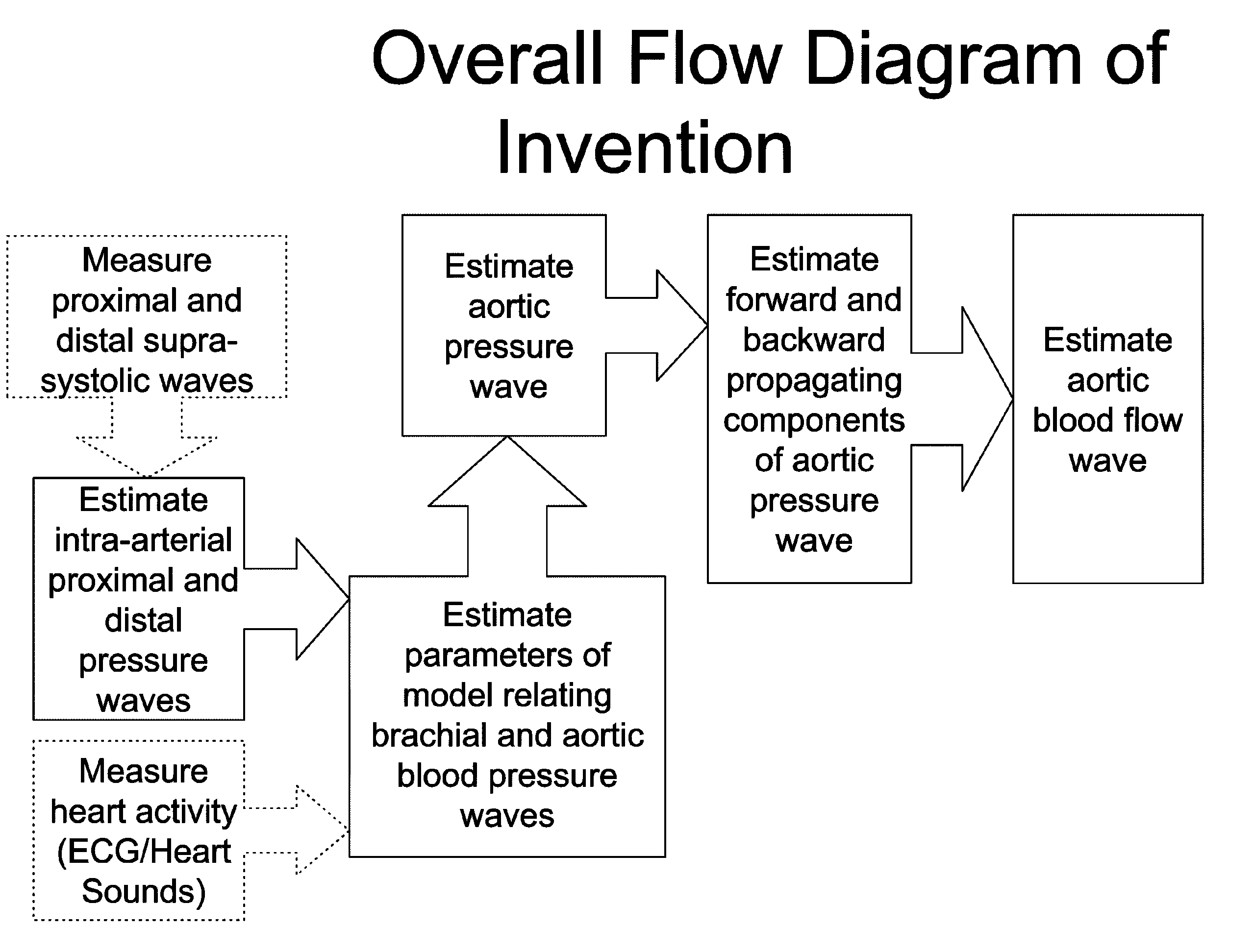
The present invention provides a better understanding and parameter identification method for a simplified physics model that can adapt to specific subjects. The invention can easily determine the time delay and reflection coefficient in the frequency domain using either a single cuff or multiple cuffs on the upper arm. The method recognizes that the aortic system is not time invariant and takes into account the additional reflection caused by the valve closure to improve the accuracy of pressure waveform estimation. The invention also allows for the estimation of the flow waveform by analyzing the pressure differential across a segment of the aorta.

Problems solved by technology

Blood pressure can also increase with an increase in arterial tone, which is the usual cause of essential hypertension.
However, the indices commonly derived from the pressure waveform are based on apparent morphology, rather than the underlying physics, there are difficulties in accurately estimating the central pressure waveform morphology from a non-invasive measurement, and it is difficult to measure the aortic flow waveform in a non-invasive manner.

Method used


Image

  • Method and apparatus for producing a central pressure waveform in an oscillometric blood pressure system
  • Method and apparatus for producing a central pressure waveform in an oscillometric blood pressure system
  • Method and apparatus for producing a central pressure waveform in an oscillometric blood pressure system

Examples


examples

[0149]The following examples have been taken from knee replacement operations by two protocols under epidural anesthesia with propofol sedation. During the operation a thigh tourniquet was applied. In the first protocol, the patient was given a continuous phenylephrine infusion to maintain systolic pressure between 100 and 130 mmHg. In the second protocol, the patient was given ephedrine rather than phenylephrine.

[0150]Both propofol and the epidural anesthesia have a vasodilating effect, which is also expected after deflation of the thigh tourniquet. Phenylephrine is a vasoconstrictor with little effect on cardiac contractility, whereas ephedrine acts as both a vasoconstrictor and cardiac stimulant.

[0151]The central waveform has been estimated from the suprasystolic, oscillometric waveform in each case, using the same parameters for shape correction, propagation delay and cuff reflection coefficient. The scaling of oscillometric pressure to arterial pressure was the same for all cas...


PUM


Abstract

A central arterial blood pressure waveform is developed from pressure waveforms obtained from proximal and distal blood pressure cuffs on the brachial artery of an arm that are inflated to a supra-systolic pressure, The proximal and distal cuff pressure waveforms associated with at least one cardiac ejection cycle are sensed, The propagation times of a blood pressure pulse from the entry of the artery to the proximal cuff and from the proximal cuff to the distal cuff are calculated, permitting calculation of a reflection coefficient of the pressure pulse at one of the proximal and distal cuffs. Assuming a physical model of wave propagation along the artery between the aorta and the proximal and distal cuffs, an estimated pressure waveform at the opening of the artery can be determined.

Description

CROSS-REFERENCE TO RELATED APPLICATIONS[0001]This present application is a continuation-in-part of U.S. patent application Ser. No. 12 / 455,516, filed Jun. 3, 2009; U.S. patent application Ser. No. 11 / 358,283, filed Feb. 21, 2006 (now U.S. Patent Publication No. 2006 / 0224070-A1, published Oct. 5, 2006, and now abandoned); U.S. patent application Ser. No. 12 / 157,854, filed Jun. 13, 2008 (now U.S. Patent Publication No. 2009 / 0012411-A1, published Jan. 8, 2009) and claims priority from U.S. Provisional Application Ser. No. 61 / 201,540, filed Dec. 11, 2008. The invention disclosed and claimed herein is related in subject matter to that disclosed in U.S. Pat. No. 5,913,826, issued Jun. 22, 1999; U.S. Pat. No. 6,994,675, issued Feb. 7, 2006; and the aforementioned U.S. Patent Publication No. 2006 / 0224070-A1 and U.S. Patent Publication No. 2009 / 0012411-A1, all of which are incorporated herein by reference.BACKGROUND OF THE INVENTION[0002]Blood pressure is the net result of stroke volume and ...

Claims


Application Information

Patent Timeline
IPC IPC(8): A61B5/021A61B5/029A61B5/00G06K9/00G06F19/00
CPCA61B5/021A61B5/02125A61B5/412G06K9/0053A61B5/029G06F19/3406G16H40/63A61B7/00G06F2218/10A61B5/022A61B5/02225A61B7/04
Inventor LOWE, ANDREW
Owner USCOM
Learn More