
Electromagnetic pump device

a technology of electromagnetic pump and electromagnetic pump, which is applied in the direction of pump components, positive displacement liquid engines, liquid fuel engine components, etc., can solve the problems and achieve the effect of increasing the size of electromagnetic pump devices

Active Publication Date: 2016-08-30
AISIN AW CO LTD
View PDF15 Cites 0 Cited by
  • Summary
  • Abstract
  • Description
  • Claims
  • Application Information

AI Technical Summary

Benefits of technology

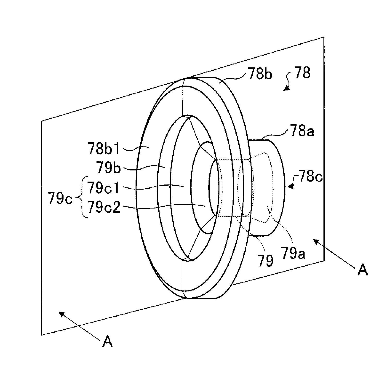
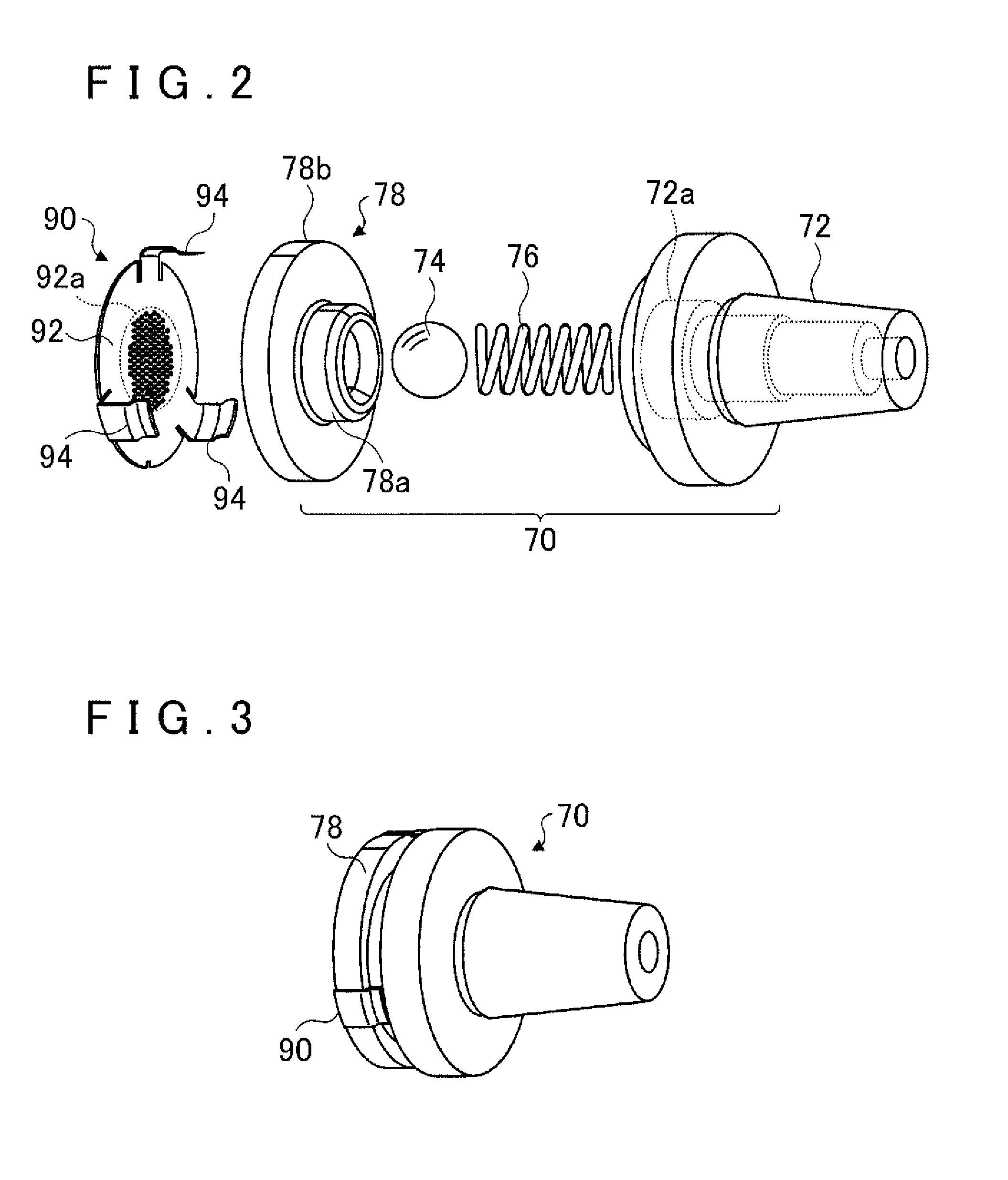
The present invention is an electromagnetic pump device with a compact configuration that can smoothly suck a working fluid. The device includes a suction check valve with a tubular portion and a flange portion, which has a through hole with a reduced diameter, which is tapered to provide a smooth suction of the working fluid. The device also includes a strainer to protect the pump from damage caused by the working fluid. The diameter reducing portion formed in the suction check valve allows for a smooth suction of the working fluid without increasing the size of the device. The invention also provides a method for smoothly sucking the working fluid and a compact electromagnetic pump device with a smooth suction check valve.

Problems solved by technology

In order to provide the stepped portion, however, it is necessary to make the suction port of the inlet check valve mechanism slightly larger in inside diameter and then expand the inlet check valve mechanism in the axial direction, which may make the inlet check valve mechanism larger to lead to an increase in size of the electromagnetic pump device.

Method used


Image

  • Electromagnetic pump device
  • Electromagnetic pump device
  • Electromagnetic pump device

Examples


Embodiment Construction

[0025]An embodiment of the present invention will be described below.

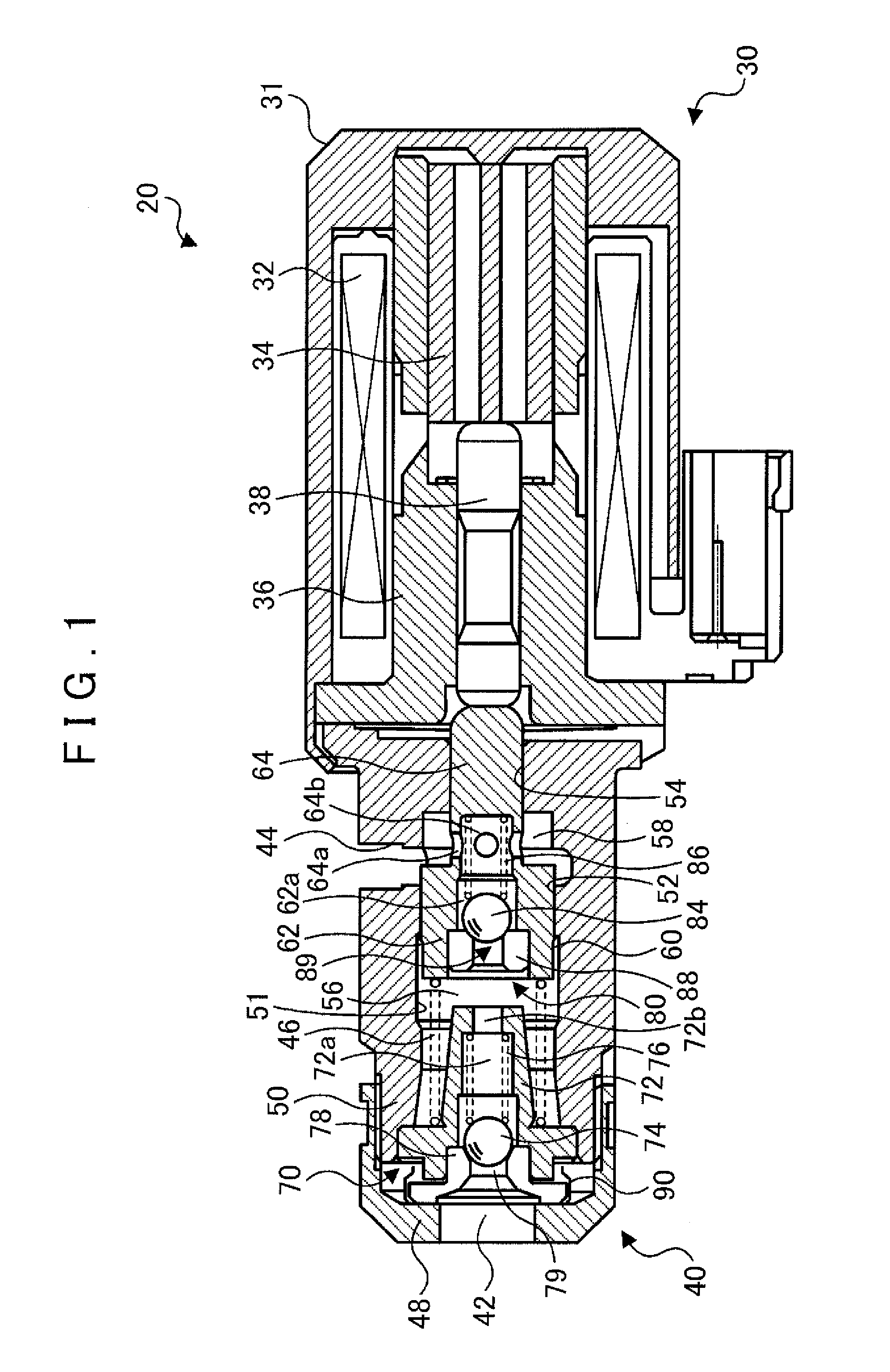
[0026]FIG. 1 is a diagram showing a schematic configuration of an electromagnetic pump 20 according to an embodiment of the present invention. The electromagnetic pump 20 according to the embodiment includes a solenoid portion 30 that generates an electromagnetic force, and a pump portion 40 actuated by the electromagnetic force of the solenoid portion 30. The electromagnetic pump 20 may be formed as a part of a hydraulic control device provided in a vehicle incorporating an engine and an automatic transmission to hydraulically drive friction engagement elements (clutches and brakes) included in the automatic transmission.

[0027]The solenoid portion 30 includes a solenoid case 31 that is a bottomed cylindrical member, an electromagnetic coil 32, a plunger 34 that serves as a movable element, and a core 36 that serves as a stationary element. The electromagnetic coil 32, the plunger 34, and the core 36 are disposed i...


PUM


Abstract

An electromagnetic pump including a suction check valve including a tubular portion and a flange portion that extends in a radial direction from an end edge of the tubular portion, the suction check valve being formed with a through hole that penetrates the tubular portion and the flange portion to form a suction port in an end surface of the flange portion. A strainer attached to the suction port and having a pore forming region which is larger than an inside diameter of the through hole at the tubular portion and in which a large number of pores are formed. The suction check valve is formed with a diameter reducing portion formed such that the inside diameter of the through hole is reduced from the flange portion toward the tubular portion with a degree of diameter reduction varied from a large value to a small value.

Description

INCORPORATION BY REFERENCE[0001]The disclosure of Japanese Patent Application No. 2011-183147 filed on Aug. 24, 2011 including the specification, drawings and abstract is incorporated herein by reference in its entirety.BACKGROUND OF THE INVENTION[0002]The present invention relates to an electromagnetic pump device in which a strainer is attached to a suction port.DESCRIPTION OF THE RELATED ART[0003]Hitherto, there has been proposed an electromagnetic pump device of this type, including an electromagnetic portion, a movable iron core capable of moving back and forth in the axial direction inside a pump chamber by turning on and off the electromagnetic portion, an inlet check valve mechanism that is built in the pump chamber and that allows working oil to flow in one direction from a suction port into the pump chamber, and an outlet check valve mechanism that is built in the pump chamber and that allows working oil to flow in one direction from the pump chamber to a discharge port (s...

Claims


Application Information

Patent Timeline
Patent Type & Authority Patents(United States)
IPC IPC(8): F04B53/10F04B17/04F04B53/20F04B53/12
CPCF04B17/044F04B53/126F04B17/04F04B53/1002F04B53/20F04B17/042
Inventor ISHIKAWA, KAZUNORINAKAI, MASAYA
Owner AISIN AW CO LTD
Learn More